
- Serial Communication
- Baud Rate
- TTL (Transistor-Transistor Logic)
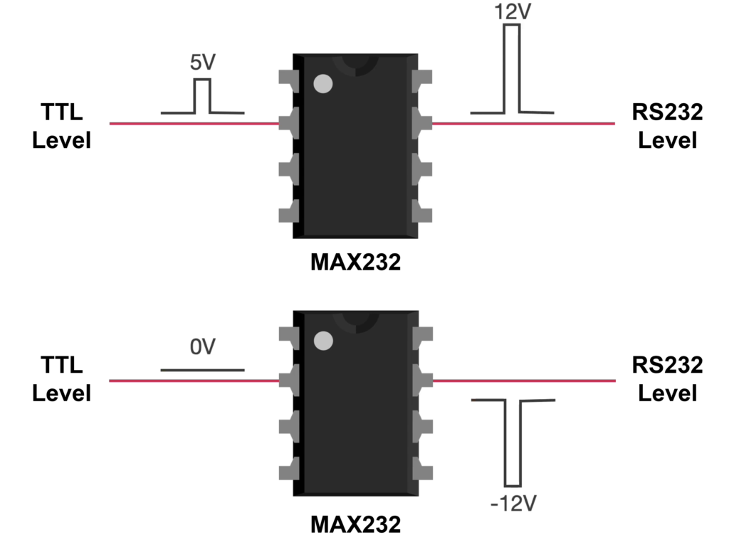
- RS-232 (Recommended Standard 232)
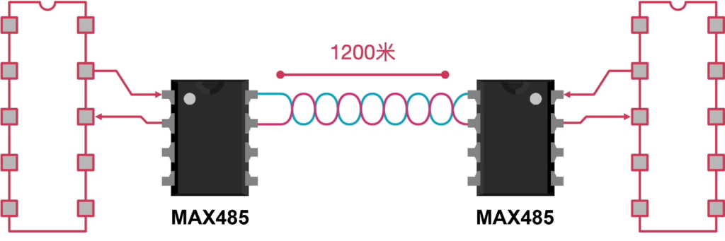
- RS-485 (Recommended Standard 485)
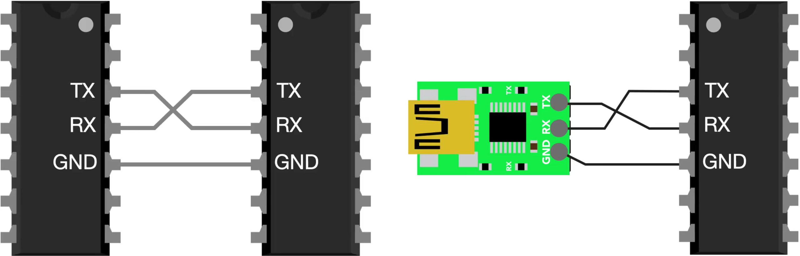
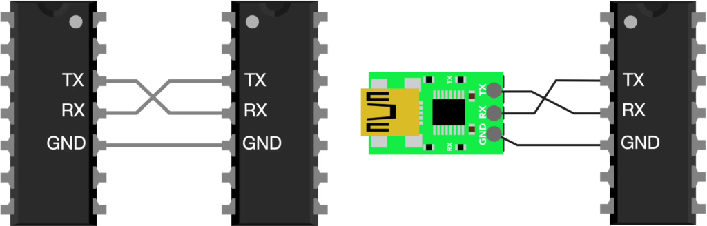
Serial communication sends data one bit at a time in sequence, as opposed to parallel communication which sends multiple bits simultaneously on multiple wires.
| Feature | SCI | UART | USART |
|---|---|---|---|
| Name | Serial Communication Interface | Universal Asynchronous Receiver/ Transmitter | Universal Synchronous/ Asynchronous Receiver/ Transmitter |
| Mode | Asynchronous only | Asynchronous only | Asynchronous and Synchronous |
| Clock | No shared clock | No shared clock | Optional shared clock (sync mode) |
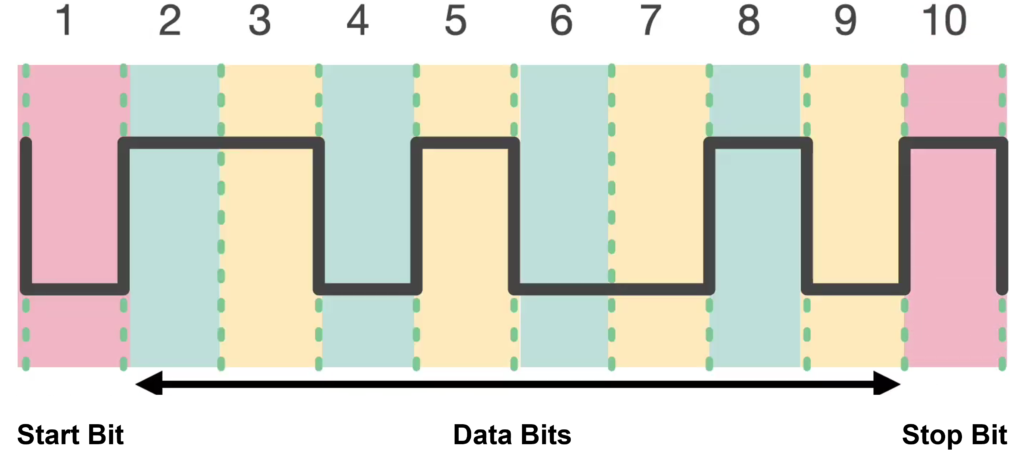
| Frame | Start bit, data bits, optional parity, stop bit(s) | Start bit, data bits, optional parity, stop bit(s) | Same as UART (async); clocked data in sync mode |
| Data Bits | 8 bits (commonly) | 5-9 bits | 5-9 bits |
| Parity | Optional | Optional | Optional |
| Stop Bits | 1 or 2 | 1, 1.5, or 2 | 1 or 2 |
| Duplex | Full duplex | Full duplex | Full duplex |
| Vendor | TI C2000, TI MSP430 | ARM MCUs, ESP32, Raspberry Pi | STM32, NXP, Atmel |
Simplex: One-way communication only — data flows in one direction (TX → RX).
Half-Duplex: Two-way communication, but only one side can transmit at a time.
Full-Duplex: Two-way communication simultaneously — both sides transmit at once.
Baud rate: is a measure of how fast data is transmitted over a communication link. It refers to the number of signal changes (symbols) per second on the communication line. Each change in signal state is one baud.
| Baud Rate (bps) | Typical Usage |
|---|---|
| 9600 | Most common default for MCU debug & modules |
| 19200 | Industrial control, PLCs |
| 38400 | Embedded systems, bootloaders |
| 57600 | High-speed MCU debug |
| 115200 | Very common for firmware flashing & logging |
| 921600 | Near practical UART limit on many systems |
| 2,000,000 | High-performance MCUs / SoCs |
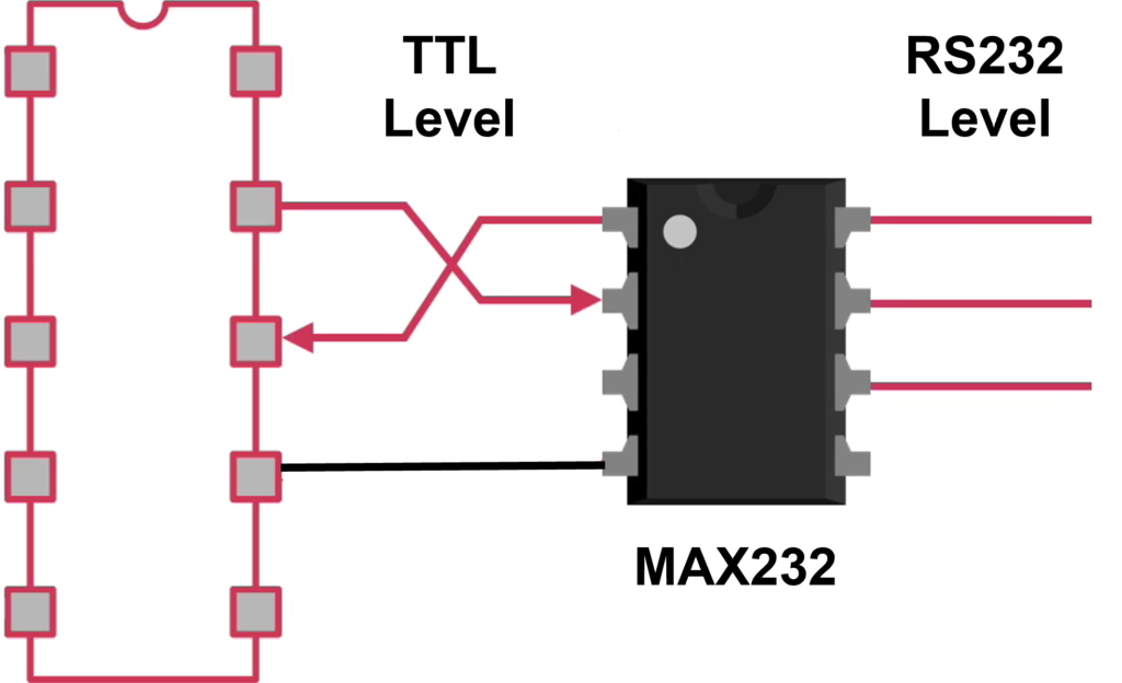
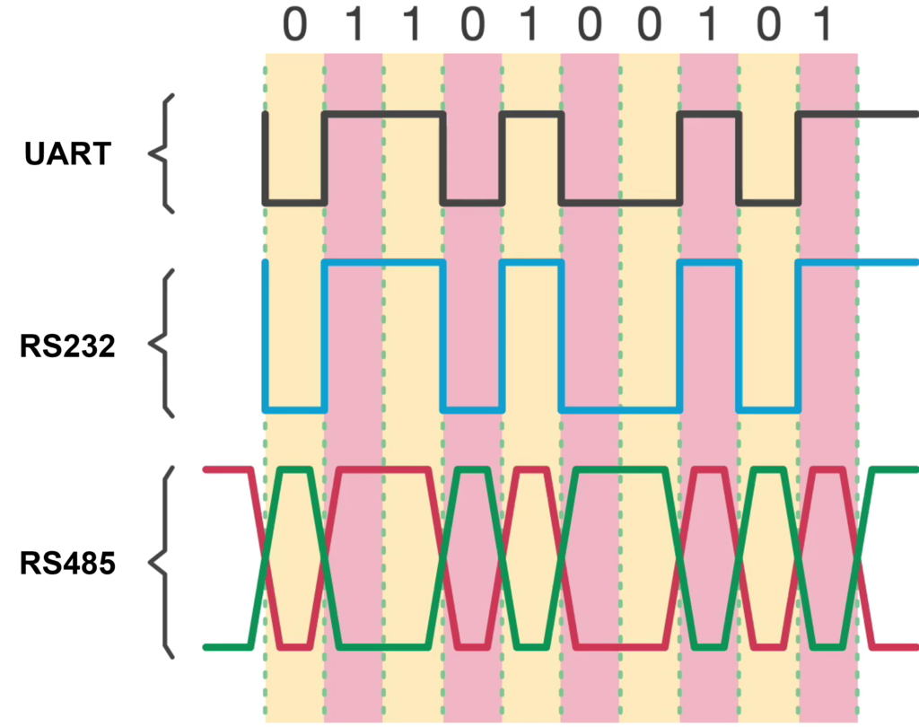
TTL (Transistor-Transistor Logic) is a digital logic family and signal level standard used in electronic circuits to represent binary values (0 and 1) using voltage levels on wires.
- Logic LOW output: up to ~0.4 V
- Logic HIGH output: ~2.4 V to 5 V
RS-232 (Recommended Standard 232) is a long-established electrical interface standard used for serial communication between two devices such as computers, modems, industrial controllers, and peripherals. It defines how binary data are transmitted one bit at a time over a cable, the physical voltage levels, connector types, and pin assignments.
- Logic LOW output: -3 V to -15 V
- Logic HIGH output: 3 V to 15 V
RS-485 (Recommended Standard 485) is a widely used serial communication electrical standard that defines how devices transmit and receive binary data over a shared bus using differential signaling — especially in industrial and automation systems. RS-485 uses two signal wires (often called A and B) that carry complementary voltages. Data is not read relative to ground, but by the voltage difference between these two wires. This method provides strong noise immunity, because interference that affects both wires equally tends to cancel out.
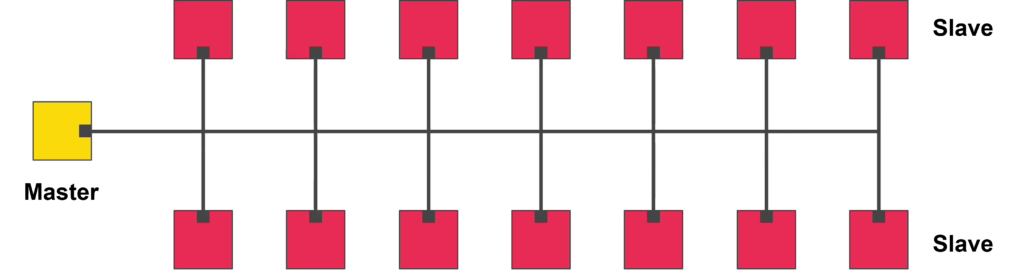
A Master device is the controller or initiator of communication on the RS-485 bus:
- It starts every transaction by sending a request or command.
- It may address a specific Slave using that device’s unique address.
- After sending a request, the Master waits for a response from the targeted Slave.
- There is only one Master on the RS-485 loop in typical master-slave protocols.
[1] 串口 RS232 RS485最本质的区别
[2] ASCII Table
Back to top of the page