
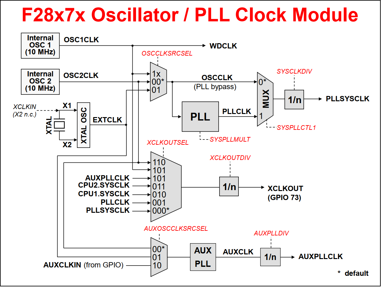
- Oscillator / PLL Clock Module
- Dual-Core System Clock
- Watchdog Timer
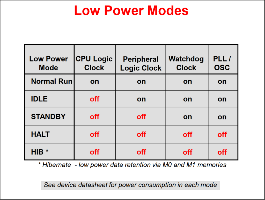
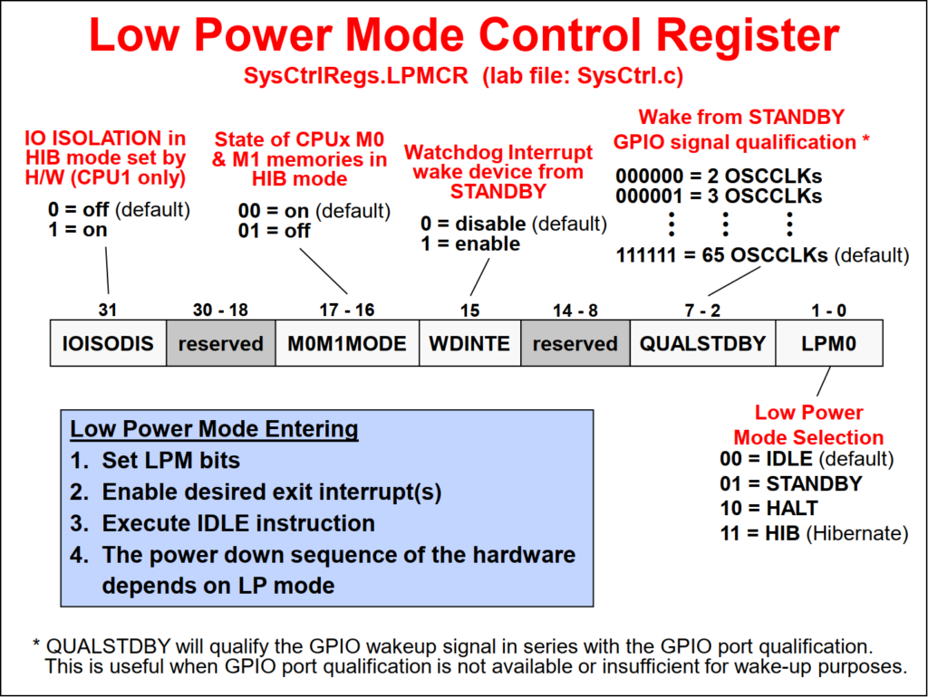
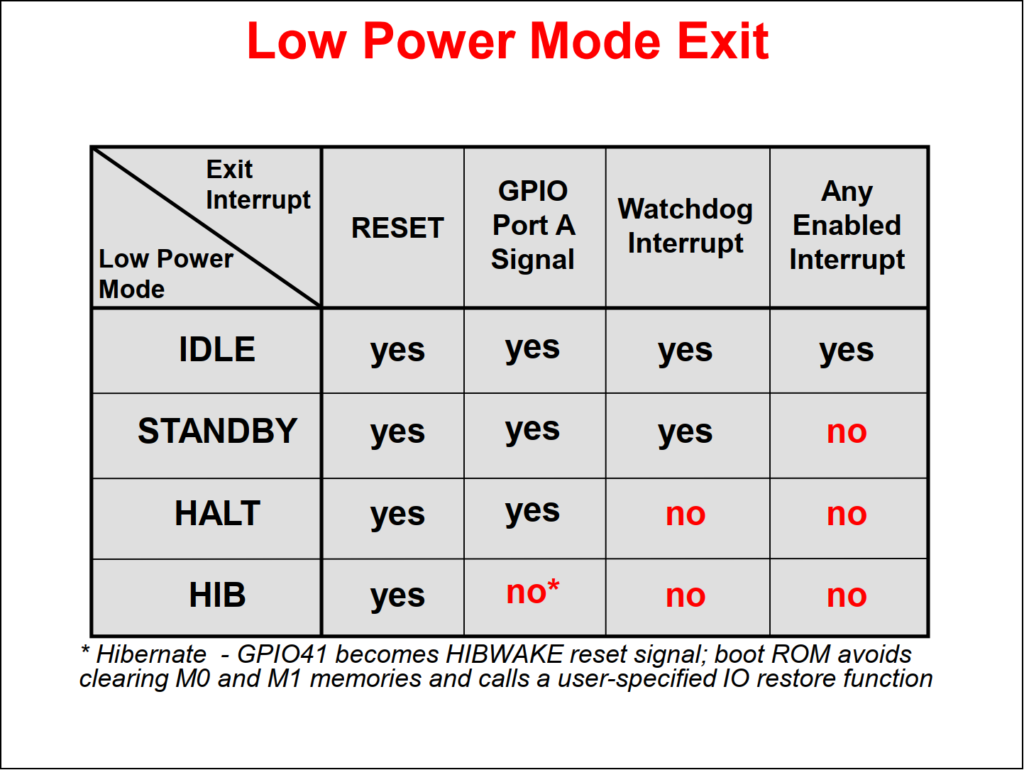
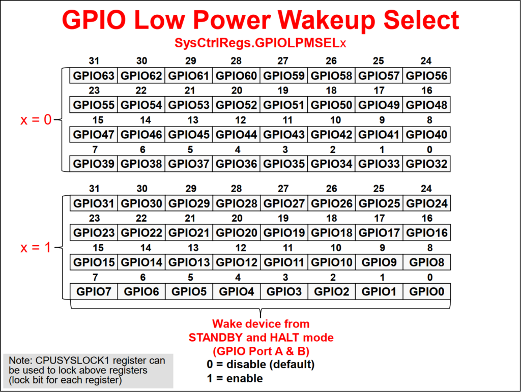
- Low Power Modes
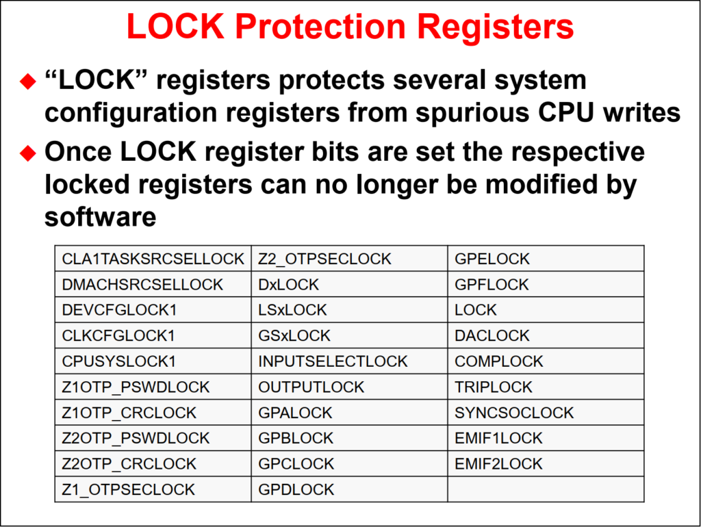
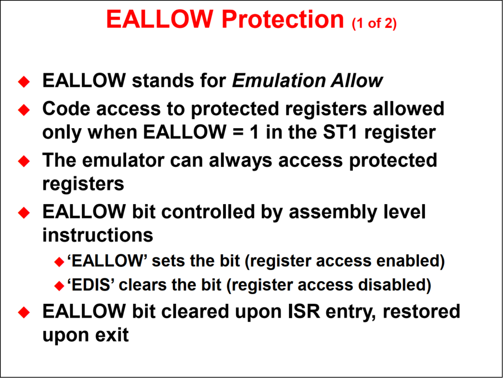
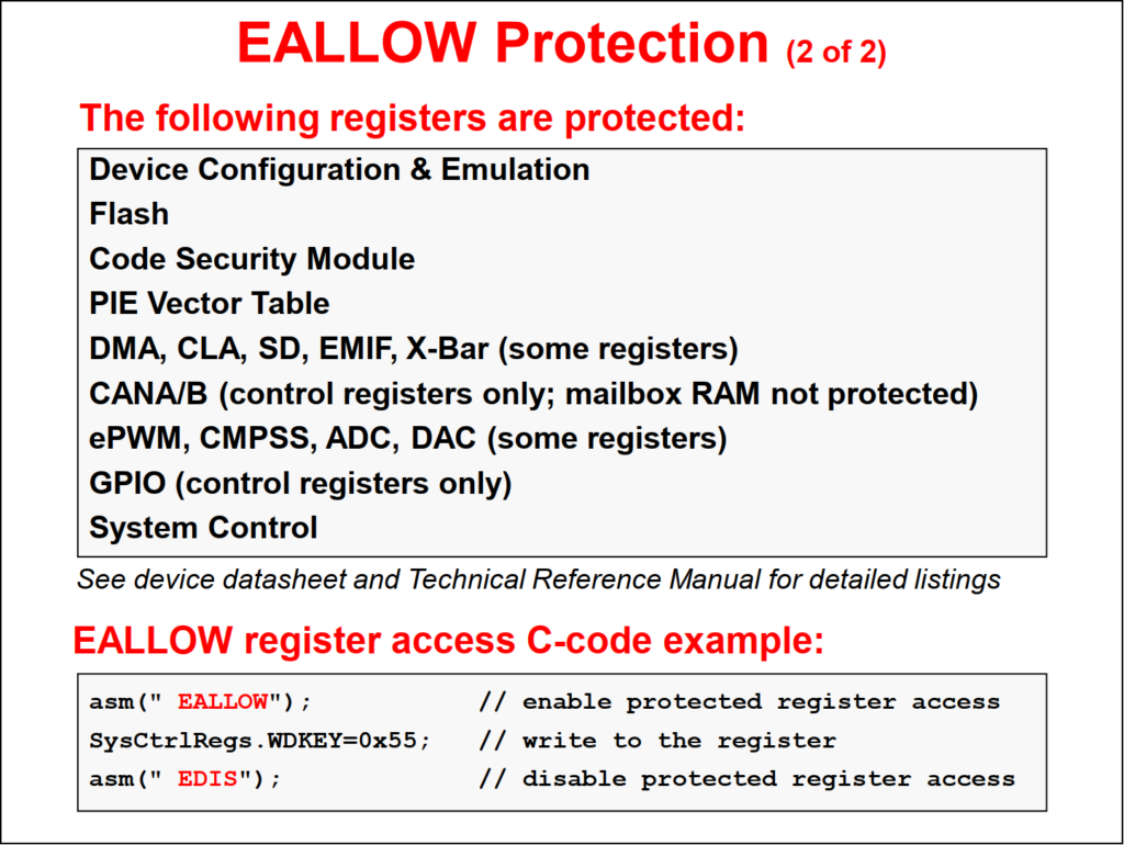
- Register Protection
The device clock signals are derived from one of four clock sources:
- Internal Oscillator 1 (INTOSC1)
- Internal Oscillator 2 (INTOSC2)
- External Oscillator (XTAL)
- Auxiliary Clock Input (AUXCLKIN)
At power-up, the device is clocked from the on-chip 10 MHz oscillator INTOSC2. INTSOC2 is the primary internal clock source, and is the default system clock at reset. The device also includes a redundant on-chip 10 MHz oscillator INTOSC1. INTOSC1 is a backup clock source, which normally only clocks the watchdog timers and missing clock detection circuit.
Additionally, the device includes dedicated X1 and X2 pins for supporting an external clock source such as an external oscillator, crystal, or resonator. The AUXCLKIN is used as the bit clock source for the USB and CAN to generate the precise frequency requirements.

The clock sources can be multiplied using the PLL and divided down to produce the desired clock frequencies for a specific application. By default, the CPU1 subsystem owns the PLL clock configuration, however a clock control semaphore is available for the CPU2 subsystem to access the clock configuration registers.
A clock source can be fed directly into the core or multiplied using the PLL. The PLL gives us the capability to use the internal 10 MHz oscillator and run the device at the full clock frequency. If the input clock is removed after the PLL is locked, the input clock failed detect circuitry will issue a limp mode clock of 1 to 4 MHz. Additionally, an internal device reset will be issued. The lowspeed peripheral clock prescaler is used to clock some of the communication peripherals.
The PLL has a 7-bit integer and 2-bit fractional ratio control to select different CPU clock rates. The C28x CPU provides a SYSCLK clock signal. This signal is prescaled to provide a clock source for some of the on-chip communication peripherals through the low-speed peripheral clock prescaler. Other peripherals are clocked by SYSCLK and use their own clock prescalers for operation.
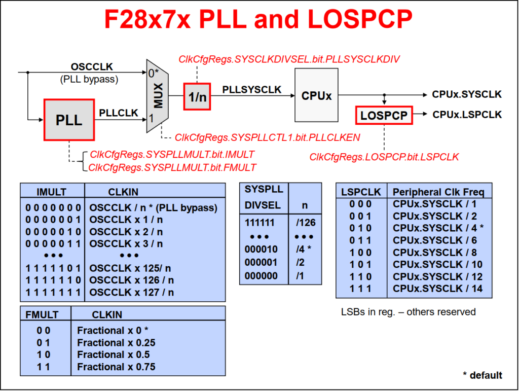
// External Oscillator (XTAL): 10 MHz
// PLLSYSCLK = (XTAL_OSC) * (IMULT + FMULT) / (PLLSYSCLKDIV)
// CPUx.SYSCLK = PLLSYSCLK = 200 MHz
// CPUx.LSPCLK = PLLSYSCLK / LSPCLKDIV = 50 MHz
ClkCfgRegs.CLKSRCCTL1.OSCCLKSRCSEL   = 0x01  // EXTCLK
ClkCfgRegs.SYSPLLMULT.bit.IMULT      = 0x28  // 40, 10 MHz x 40 = 400 MHz
ClkCfgRegs.SYSPLLMULT.bit.FMULT      = 0x00  // 0
ClkCfgRegs.SYSPLLCTL1.PLLCLKEN       = 0x01  // PLL Clock Enable
ClkCfgRegs.SYSCLKDIVSEL.PLLSYSCLKDIV = 0x01  // /2, 400 MHz / 2 = 200 MHz, SYSCLK
ClkCfgRegs.LOSPCP.LSPCLKDIV          = 0x02  // /4, 200 MHz / 4 = 50 MHz, LSPCLK

// External Oscillator (XTAL): 20 MHz
// CPUx.SYSCLK = PLLSYSCLK = 200 MHz
// CPUx.LSPCLK = PLLSYSCLK / LSPCLKDIV = 50 MHz
ClkCfgRegs.CLKSRCCTL1.OSCCLKSRCSEL   = 0x01  // EXTCLK
ClkCfgRegs.SYSPLLMULT.bit.IMULT      = 0x14  // 20, 20 MHz x 20 = 400 MHz
ClkCfgRegs.SYSPLLMULT.bit.FMULT      = 0x00  // 0
ClkCfgRegs.SYSPLLCTL1.PLLCLKEN       = 0x01  // PLL Clock Enable
ClkCfgRegs.SYSCLKDIVSEL.PLLSYSCLKDIV = 0x01  // /2, 400 MHz / 2 = 200 MHz, SYSCLK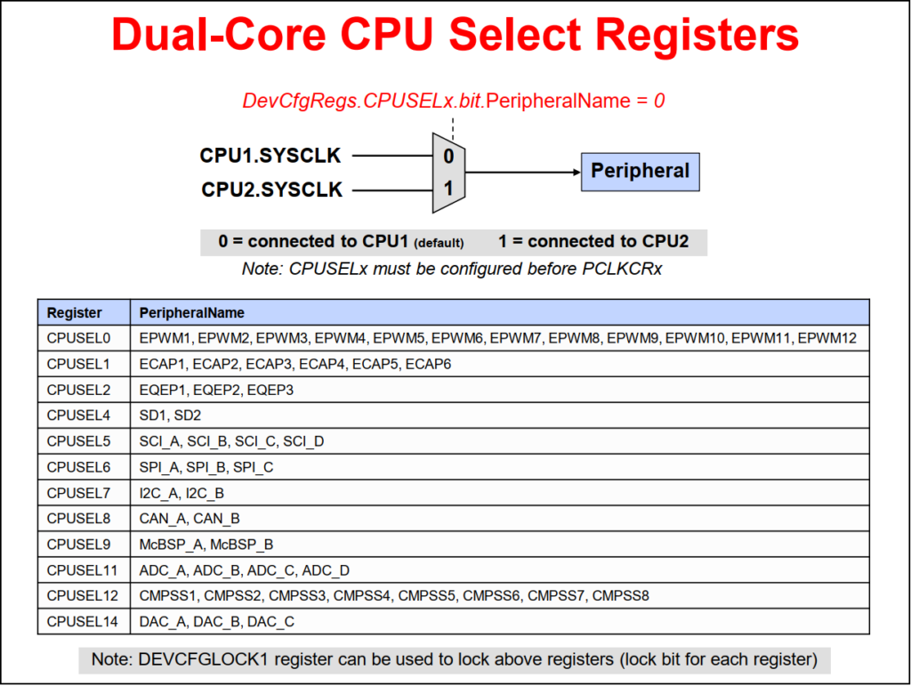
ClkCfgRegs.LOSPCP.LSPCLKDIV = 0x02 // /4, 200 MHz / 4 = 50 MHz, LSPCLKThe PLL system clock is fed to both the CPU1 and CPU2 subsystems. By default, all peripherals are assigned to the CPU1 subsystem. Using the CPU selection register, each individual peripheral can be assigned to either the CPU1 or CPU2 subsystem. The clock for the EPWM modules are limited to 100 MHz, and by using the peripheral clock divider selection register, this clock can be divided down to meet this specification.
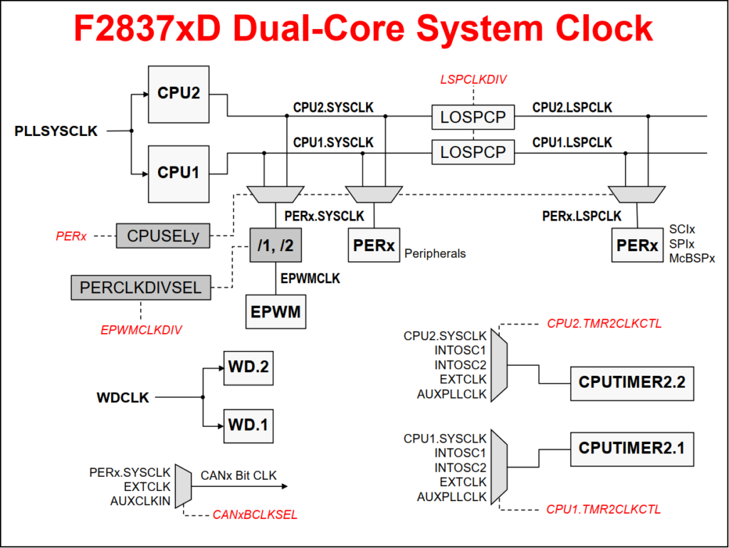
PLLSYSCLK = 200 MHz

// On F2837xD Type-4 ePWM, the ePWM module clock has its own divider
ClkCfgRegs.PERCLKDIVSEL.bit.EPWMCLKDIV = 1

// By default, EPWMCLKDIV = 1, which means:
EPWMCLK = PLLSYSCLK / 2 = 200 MHz / 2 = 100 MHz

// Inside each ePWM module, the time-base clock is further divided:
TBCLK     = EPWMCLK / (HSPCLKDIV * CLKDIV)
CLKDIV    = /1
HSPCLKDIV = /2
TBCLK     = 100 MHz / (2 * 1) = 50 MHz

// PWM frequency depends on the counting mode
PWM frequency = TBCLK / (TBPRD + 1)  // For up-count mode
PWM frequency = TBCLK / (2 × TBPRD) // For up-down count mode 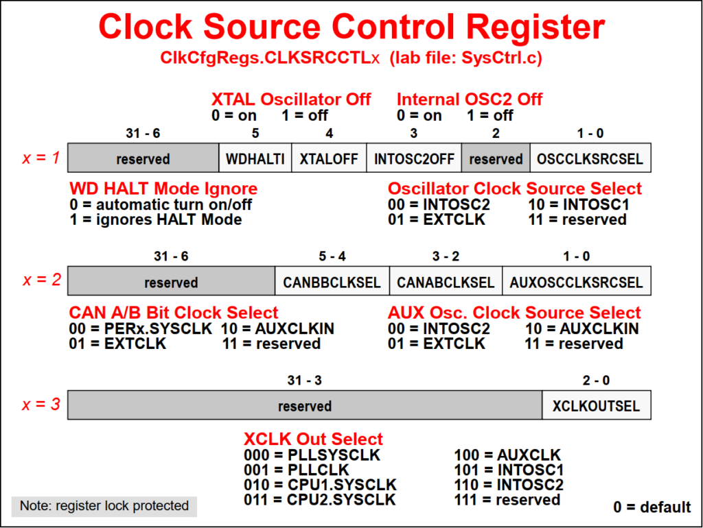
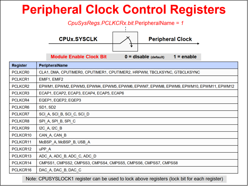
The dual-core CPU select register selects either CPU1 or CPU2 as the clock source for each peripheral. The peripheral clock control register allows individual peripheral clock signals to be enabled or disabled. If a peripheral is not being used, its clock signal could be disabled, thus reducing power consumption.
The watchdog timer is a safety feature, which resets the device if the program runs away or gets trapped in an unintended infinite loop. The watchdog counter runs independent of the CPU. If the counter overflows, a user-selectable reset or interrupt is triggered. During runtime the correct key values in the proper sequence must be written to the watchdog key register in order to reset the counter before it overflows.
Resets the C28x if the CPU crashes
- Watchdog counter runs independent of CPU
- If counter overflows, a reset or interrupt is triggered (user selectable)
- CPU must write correct data key sequence to reset the counter before overflow
The watchdog timer provides a safeguard against CPU crashes by automatically initiating a reset if it is not serviced by the CPU at regular intervals. In motor control applications, this helps protect the motor and drive electronics when control is lost due to a CPU lockup. Any CPU reset will set the PWM outputs to a high-impedance state, which should turn off the power converters in a properly designed system.
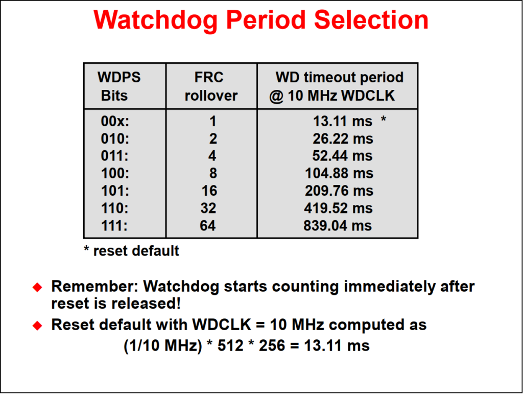
The watchdog timer starts running immediately after system power-up/reset, and must be dealt with by software soon after. Specifically, the watchdog must be serviced or disabled within 13.11 milliseconds (using a 10 MHz watchdog clock) after any reset before a watchdog initiated reset will occur. This translates into 131,072 watchdog clock cycles, which is a seemingly tremendous amount. Indeed, this is plenty of time to get the watchdog configured as desired and serviced. A failure of your software to properly handle the watchdog after reset could cause an endless cycle of watchdog initiated resets to occur.
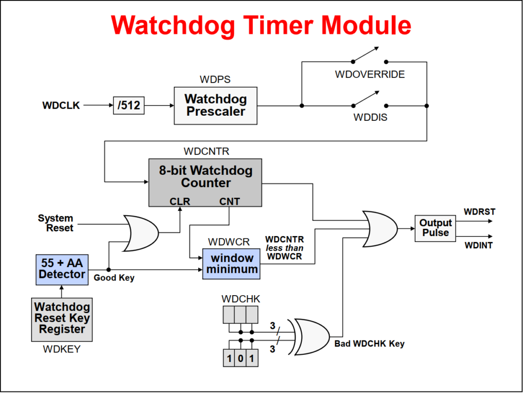
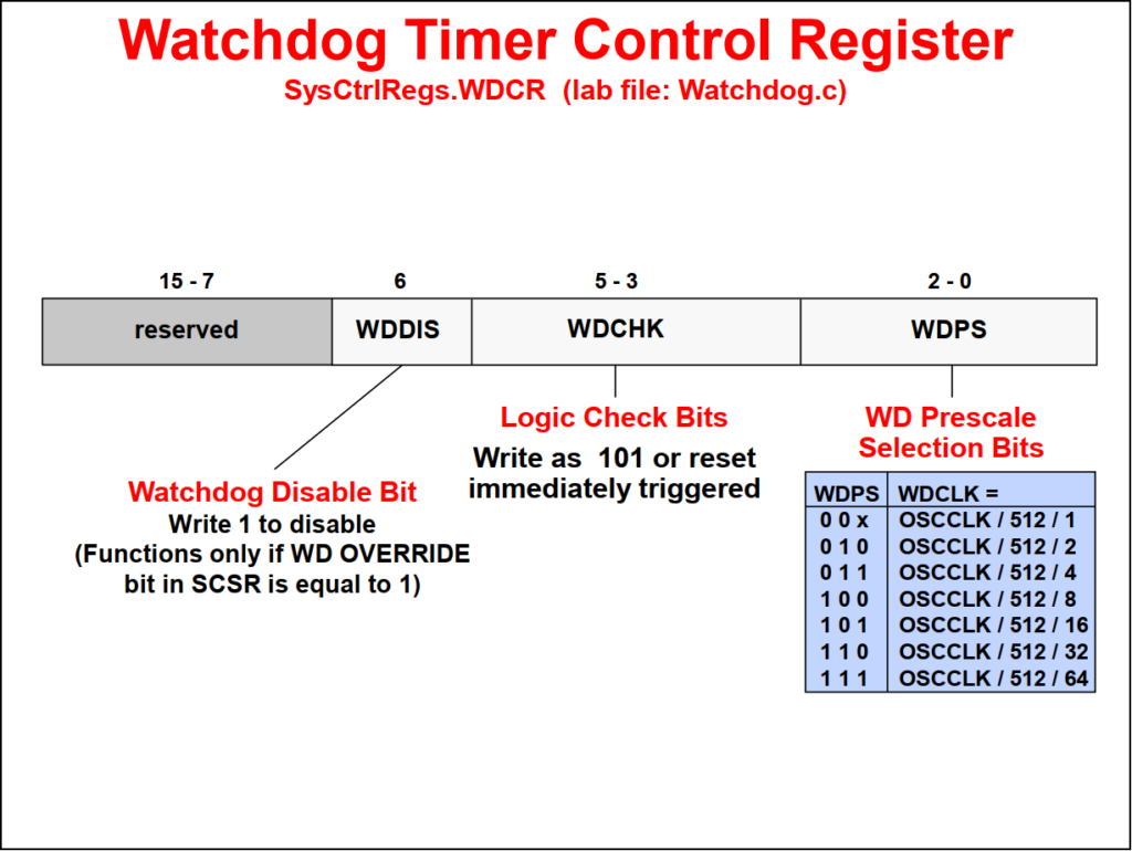
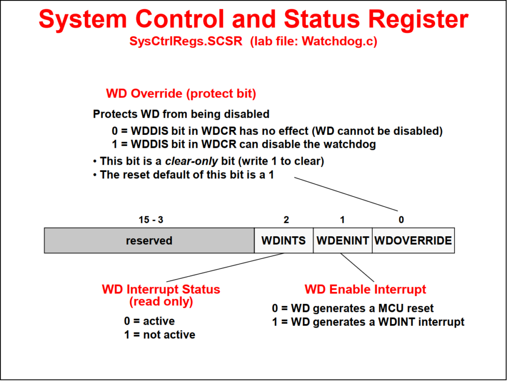
The watchdog clock is divided by 512 and prescaled, if desired for slower watchdog time periods. A watchdog disable switch allows the watchdog to be enabled and disabled. Also a watchdog override switch provides an additional safety mechanism to insure the watchdog cannot be disabled. Once set, the only means to disable the watchdog is by a system reset.
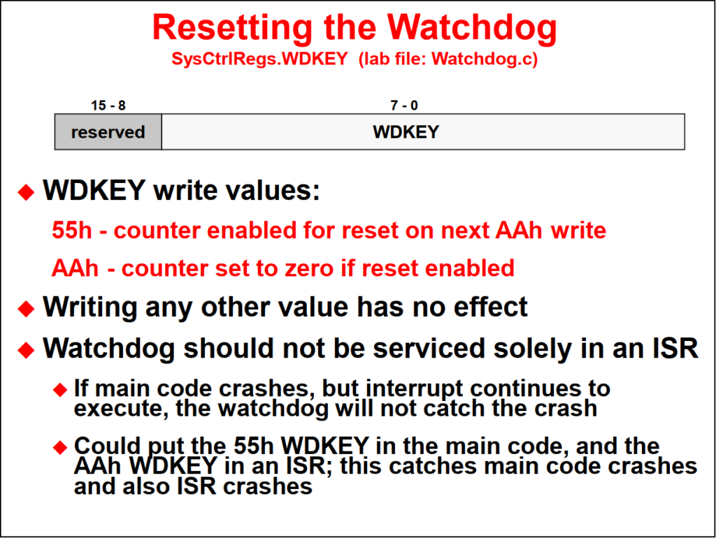
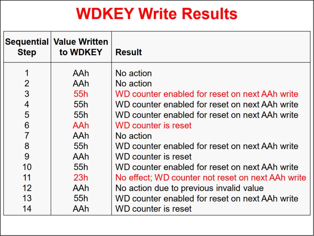
During initialization, a value 101 is written into the watchdog check bit fields. Any other values will cause a reset or interrupt. During run time, the correct keys must be written into the watchdog key register before the watchdog counter overflows and issues a reset or interrupt. Issuing a reset or interrupt is user-selectable. The watchdog also contains an optional windowing feature that requires a minimum delay between counter resets.
A series of lock registers can be used to protect several system configuration settings from spurious CPU writes. After the lock registers bits are set, the respective locked registers can no longer be modified by software.
Back to top of the page