
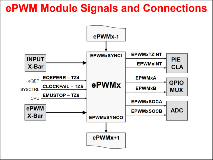
ePWM Module Signals and Connections

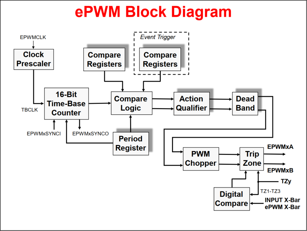
ePWM Block Diagram
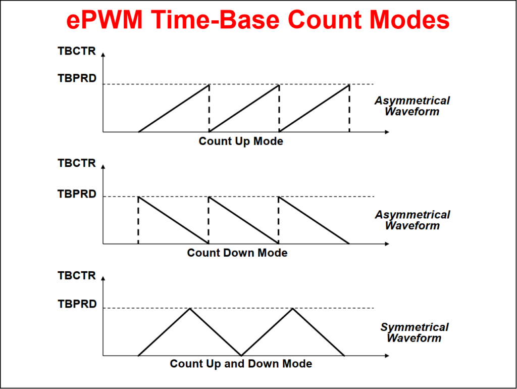
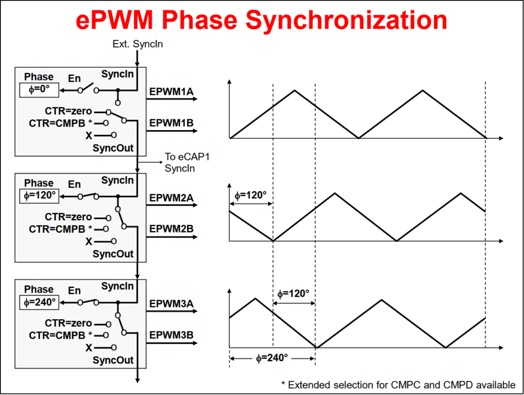
ePWM Time-Base Sub-Module
ePWM Compare Sub-Module
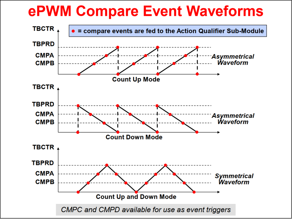
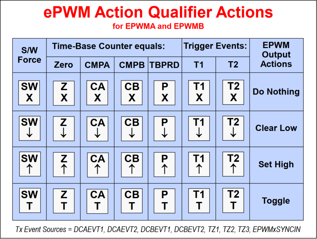
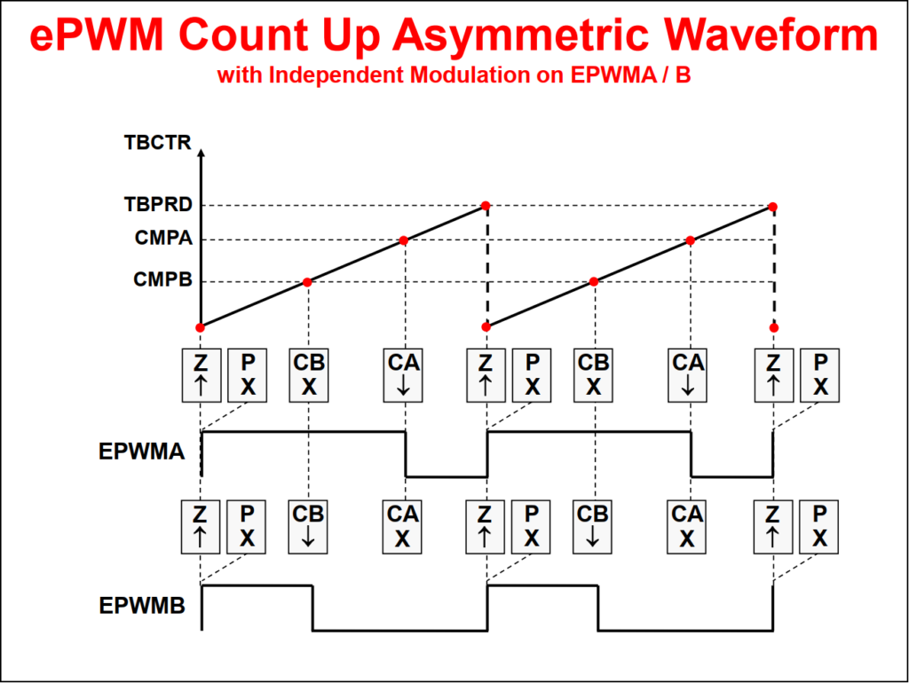
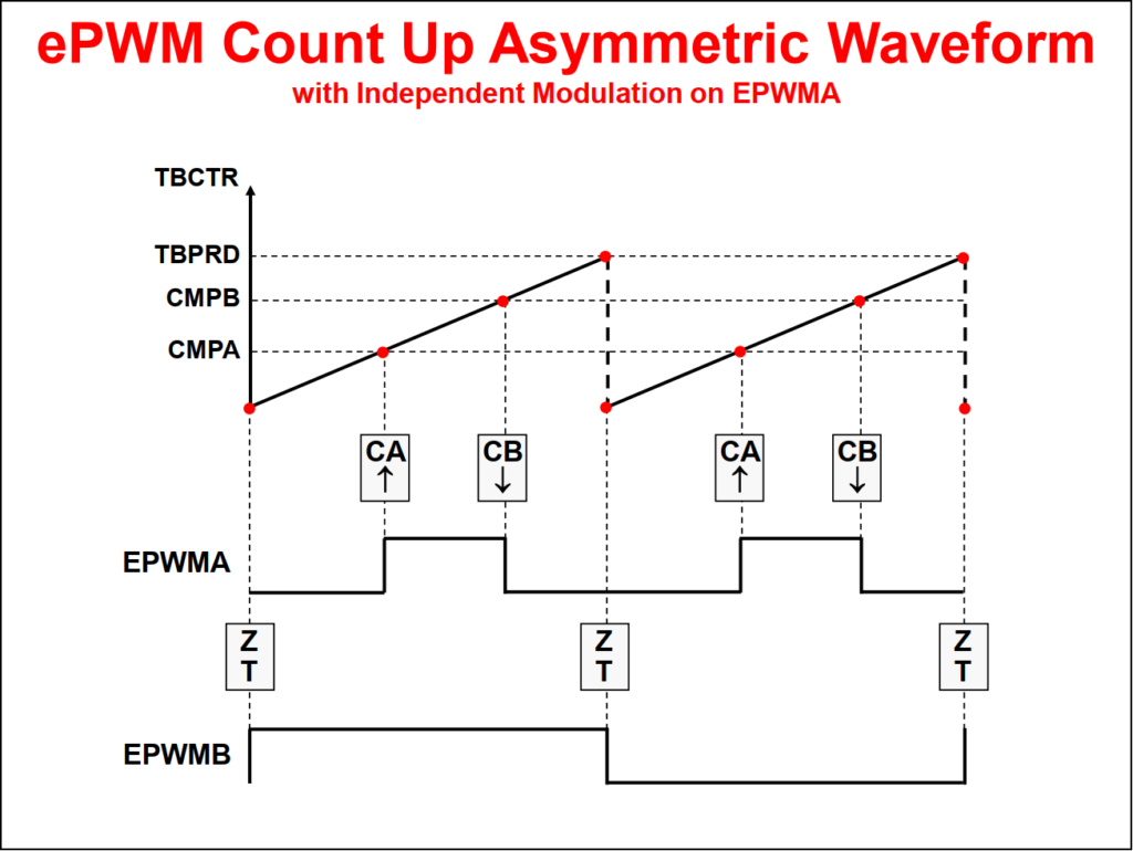
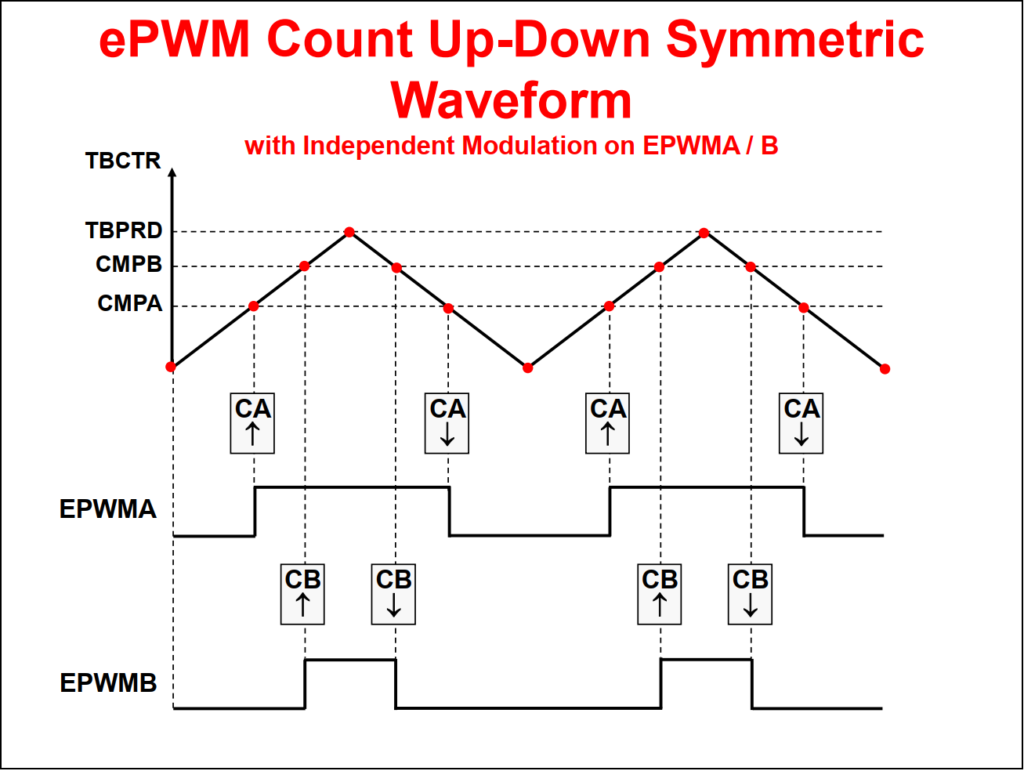
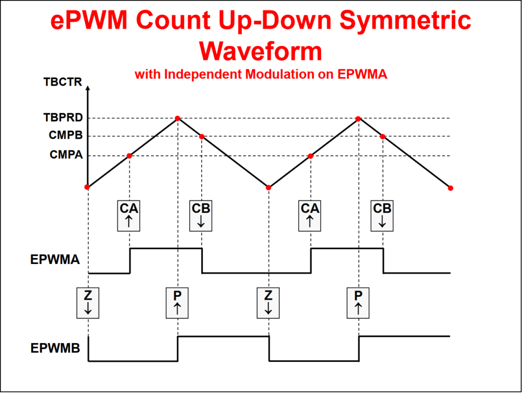
ePWM Action Qualifier Sub-Module
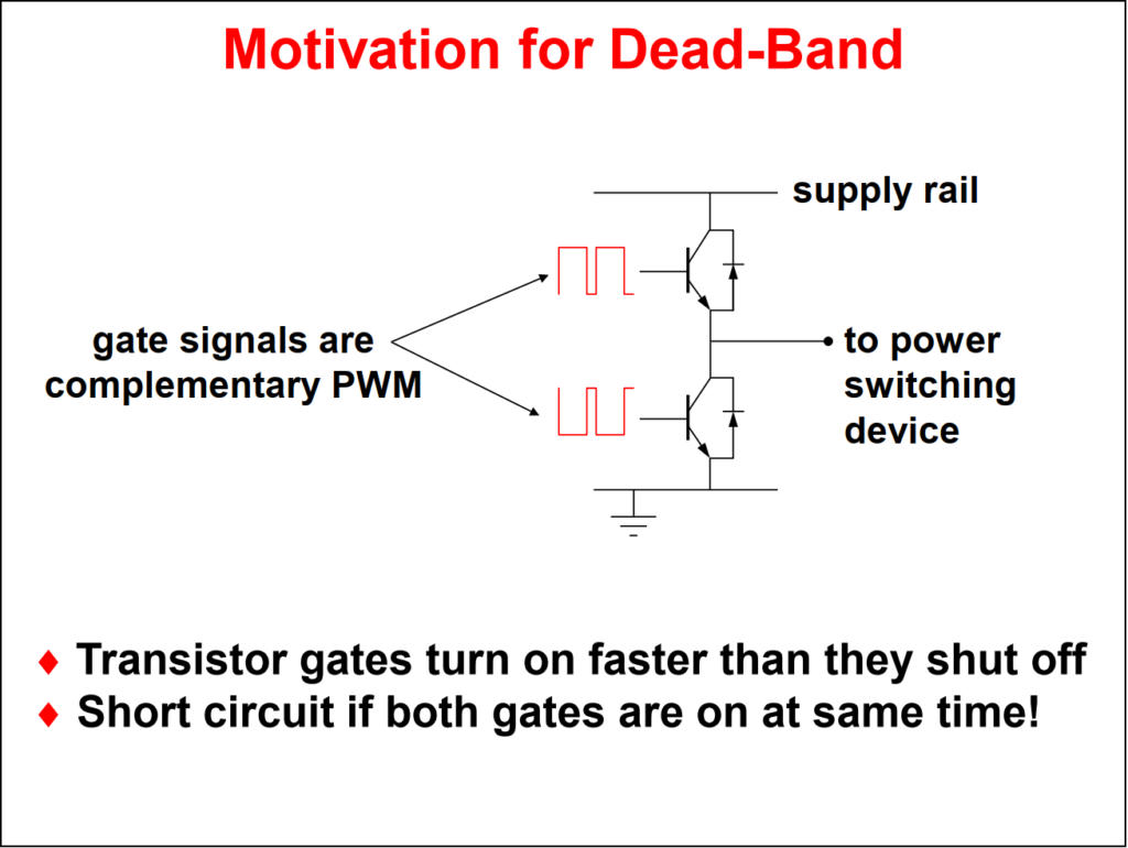
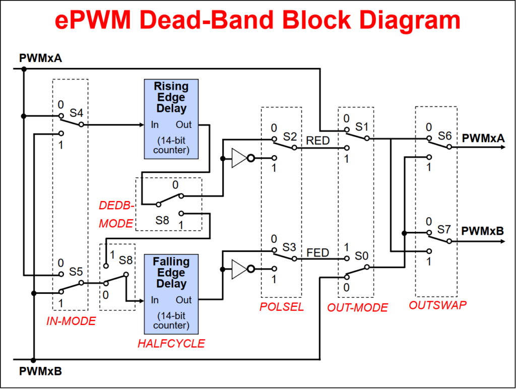
ePWM Dead-Band Sub-Module
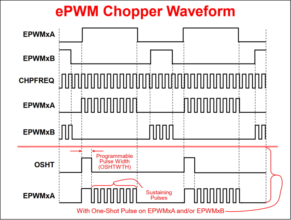
ePWM Chopper Sub-Module
Purpose of the PWM Chopper
- Allows a high frequency carrier signal to modulate the PWM waveform generated by the Action Qualifier and Dead-Band modules
- Used with pulse transformer-based gate drivers to control power switching elements
ePWM Trip-Zone and Digital Compare Sub-Module
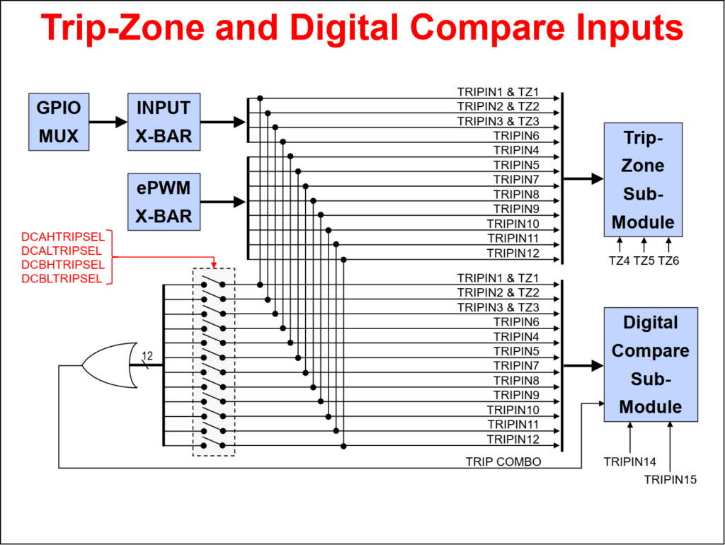
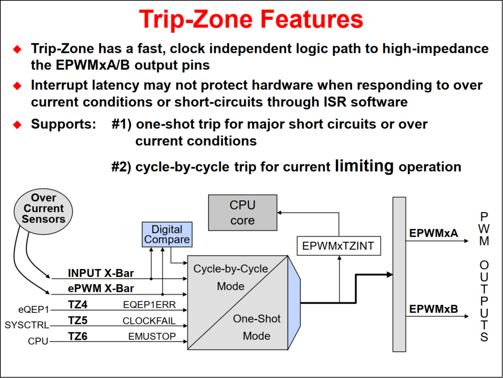
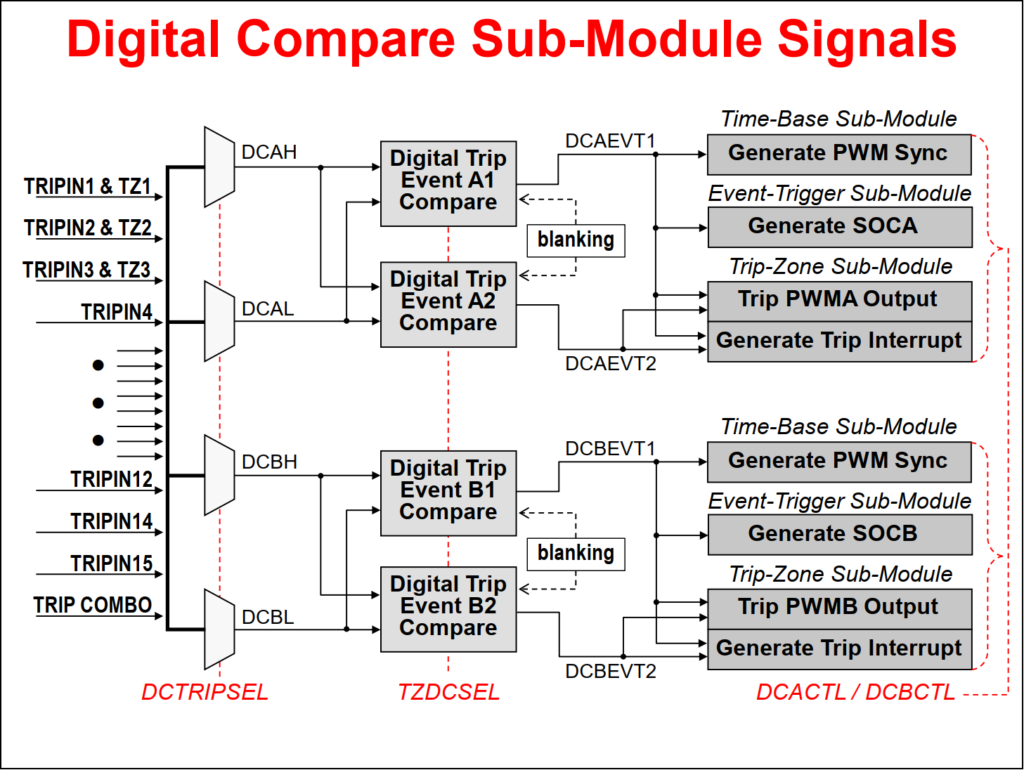
Purpose of the Digital Compare Sub-Module
-
Generates compare events that can:
- Trip the ePWM
- Generate a Trip interrupt
- Sync the ePWM
- Generate an ADC start of conversion
-
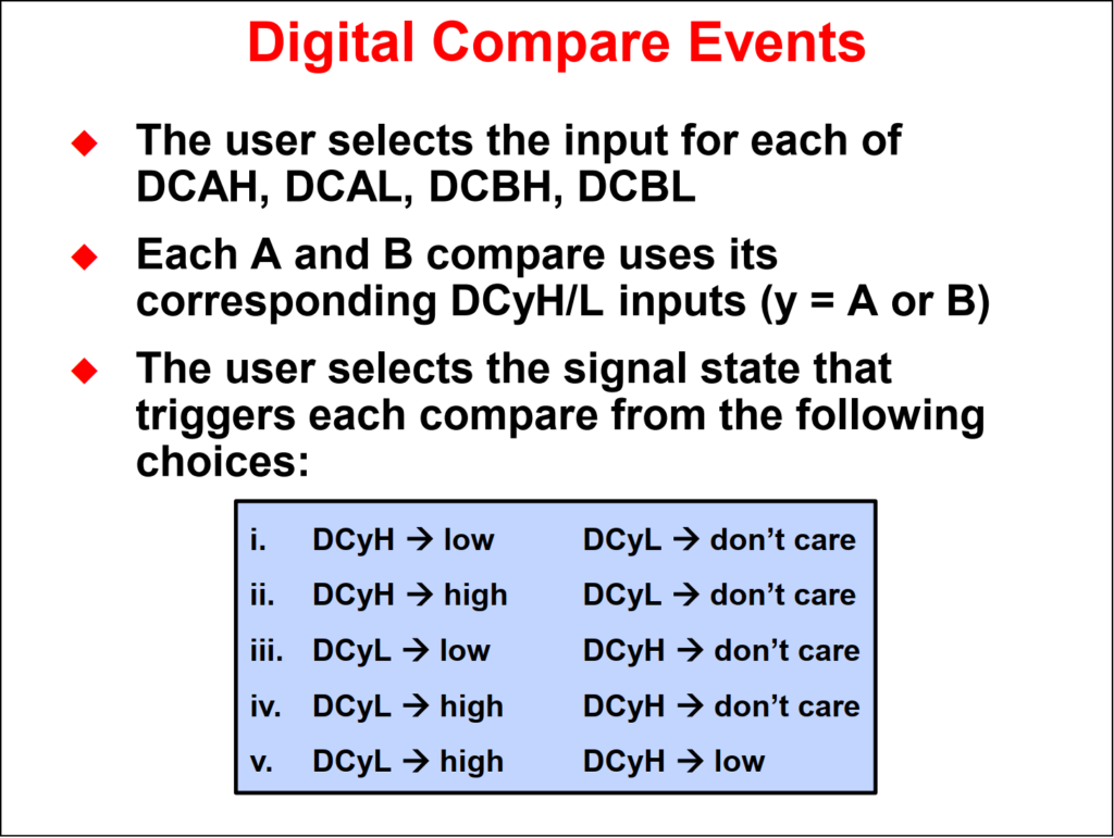
Digital compare module inputs are:
- Input X-Bar
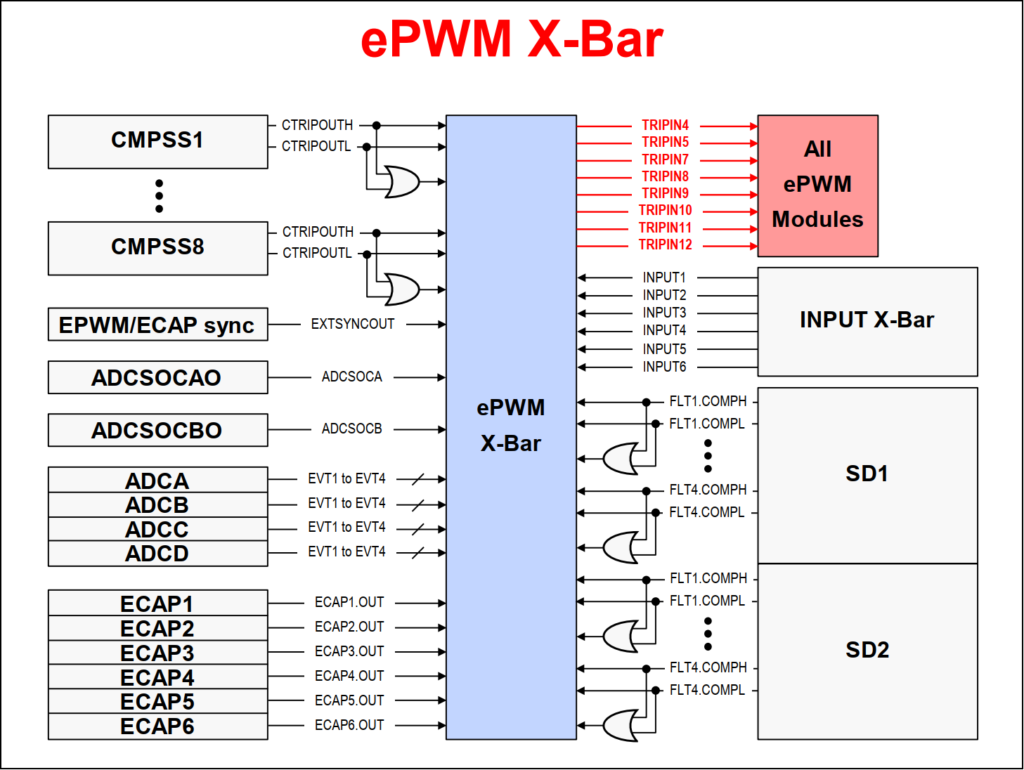
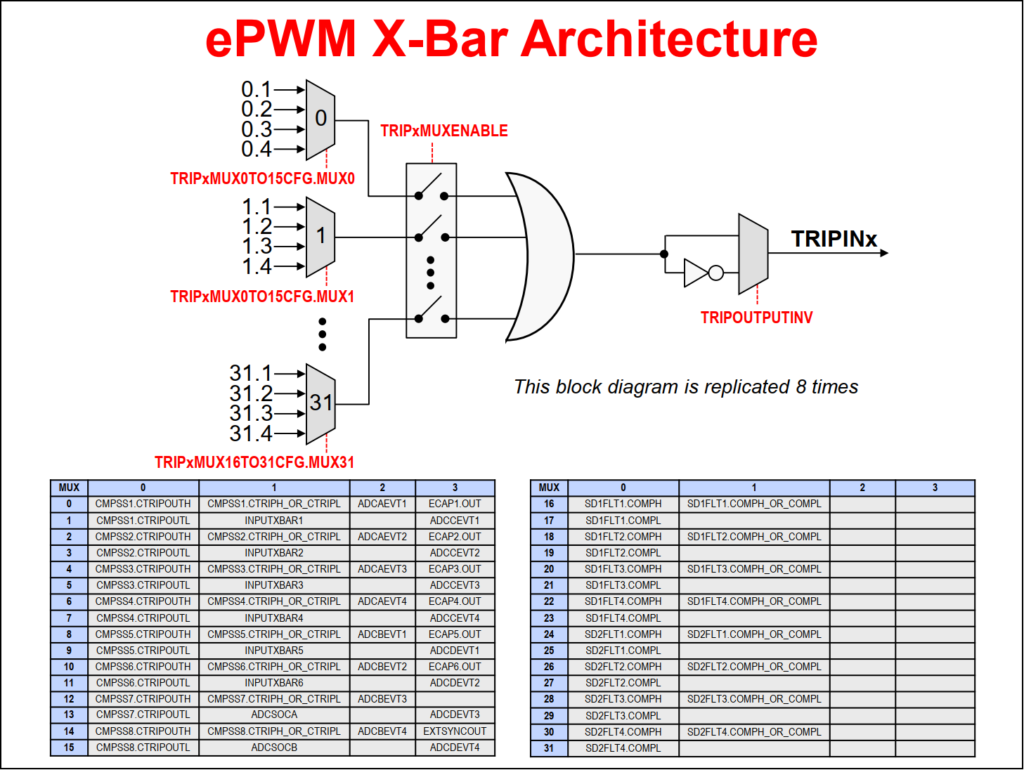
- ePWM X-Bar
- Trip-zone input pins
- A compare event is generated when one or more of its selected inputs are either high or low
- Optional Blanking can be used to temporarily disable the compare action in alignment with PWM switching to eliminate noise effects
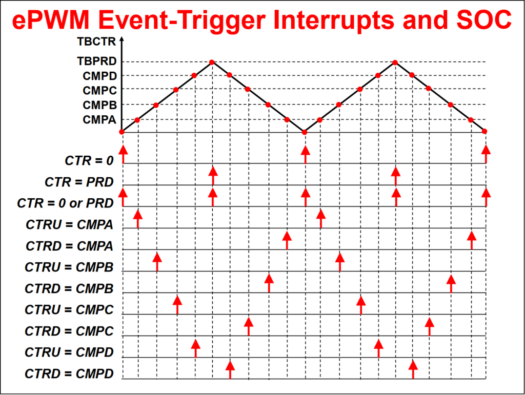
ePWM Event-Trigger Sub-Module
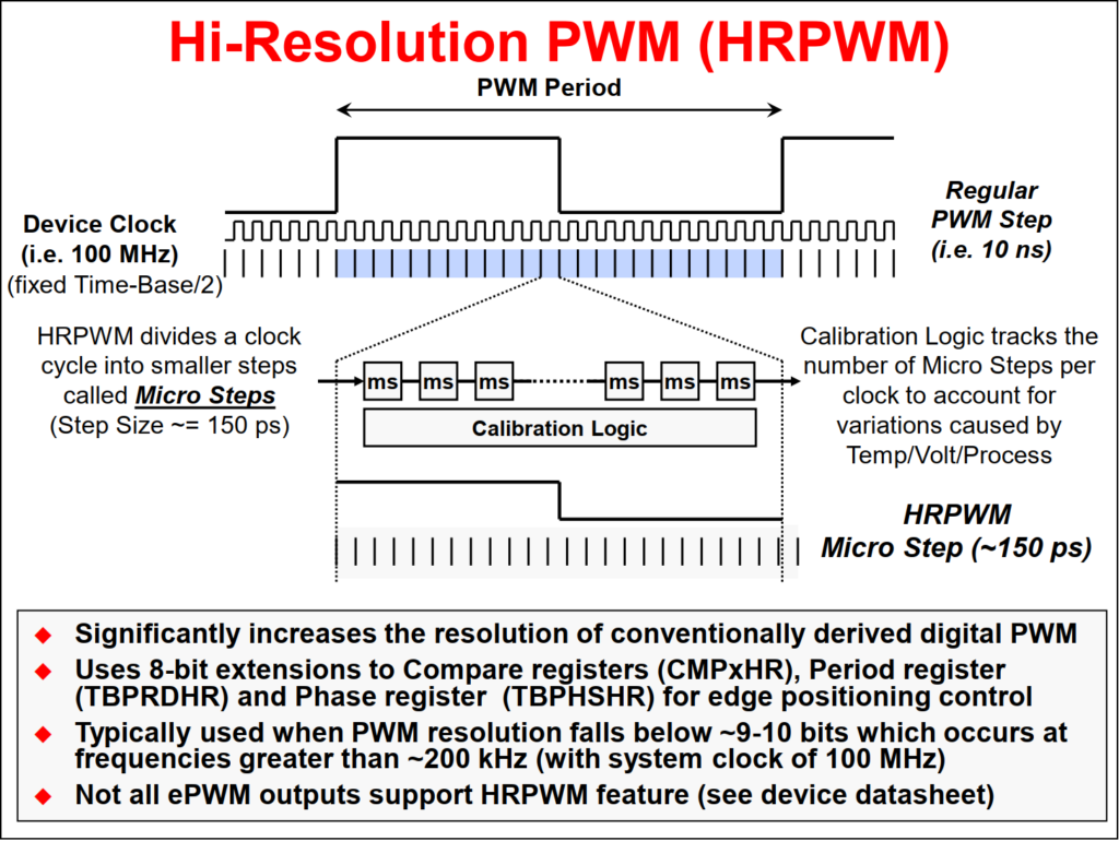
Hi-Resolution PWM (HRPWM)
Reference
Back to top of the page