
Please also see this post about the SPI communication protocol.
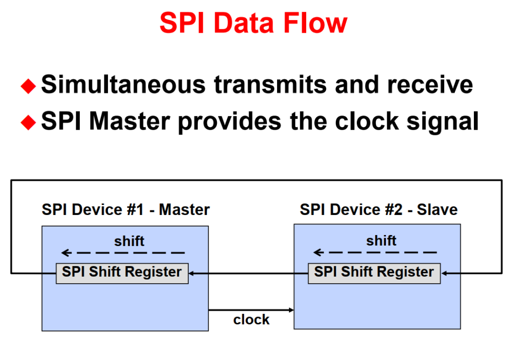
The SPI is a high-speed synchronous serial port that shifts a programmable length serial bit stream into and out of the device at a programmable bit-transfer rate. It is typically used for communications between processors and external peripherals, and it has a 16-level deep receive and transmit FIFO for reducing servicing overhead. During data transfers, one SPI device must be configured as the transfer MASTER, and all other devices configured as SLAVES. The master drives the transfer clock signal for all SLAVES on the bus. SPI communications can be implemented in any of three different modes:
- MASTER sends data, SLAVES send dummy data
- MASTER sends data, one SLAVE sends data
- MASTER sends dummy data, one SLAVE sends data
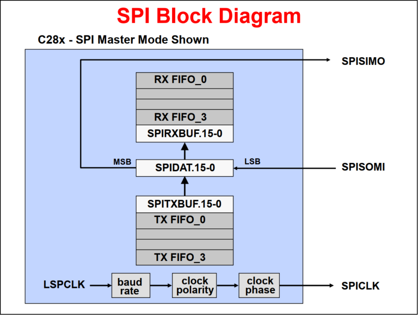
In its simplest form, the SPI can be thought of as a programmable shift register. Data is shifted in and out of the SPI through the SPIDAT register. Data to be transmitted is written directly to the SPIDAT register, and received data is latched into the SPIBUF register for reading by the CPU. This allows for double-buffered receive operation, in that the CPU need not read the current received data from SPIBUF before a new receive operation can be started. However, the CPU must read SPIBUF before the new operation is complete of a receiver overrun error will occur. In addition, double-buffered transmit is not supported: the current transmission must be complete before the next data character is written to SPIDAT or the current transmission will be corrupted.
The Master can initiate a data transfer at any time because it controls the SPICLK signal. The software, however, determines how the Master detects when the Slave is ready to broadcast.

- Slave writes data to be sent to its shift register (SPIDAT).
- Master writes data to be sent to its shift register (SPIDAT or SPITXBUF).
- Completing Step 2 automatically starts the SPICLK signal of the Master.
- The MSB of the Master’s shift register (SPIDAT) is shifted out, and the LSB of the Slave’s shift register (SPIDAT) is loaded.
- Step 4 is repeated until the specified number of bits are transmitted.
- The SPIDAT register is copied to the SPIRXBUF register.
- The SPI INT Flag bit is set to 1.
- An interrupt is asserted if the SPI INT ENA bit is set to 1.
- If data is in SPITXBUF, either Slave or Master, it is loaded into SPIDAT and transmission starts again as soon as the Master’s SPIDAT is loaded.
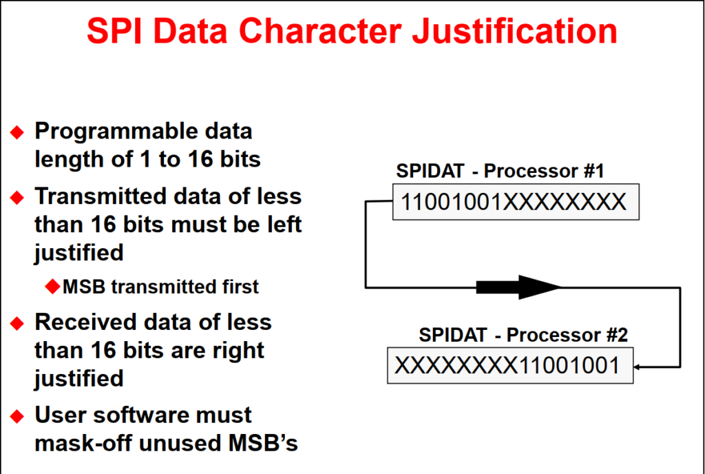
Since data is shifted out of the SPIDAT register MSB first, transmission characters of less than 16 bits must be left-justified by the CPU software prior to be written to SPIDAT.
Received data is shifted into SPIDAT from the left, MSB first. However, the entire sixteen bits of SPIDAT is copied into SPIBUF after the character transmission is complete such that received characters of less than 16 bits will be right-justified in SPIBUF. The non-utilized higher significance bits must be masked-off by the CPU software when it interprets the character. For example, a 9 bit character transmission would require masking-off the 7 MSB’s.
- Synchronous serial communications
- Two wire transmit or receive (half duplex)
- Three wire transmit and receive (full duplex)
- Software configurable as master or slave
- C28x provides clock signal in master mode
- Data length programmable from 1-16 bits
- 125 different programmable baud rates
Back to top of the page