
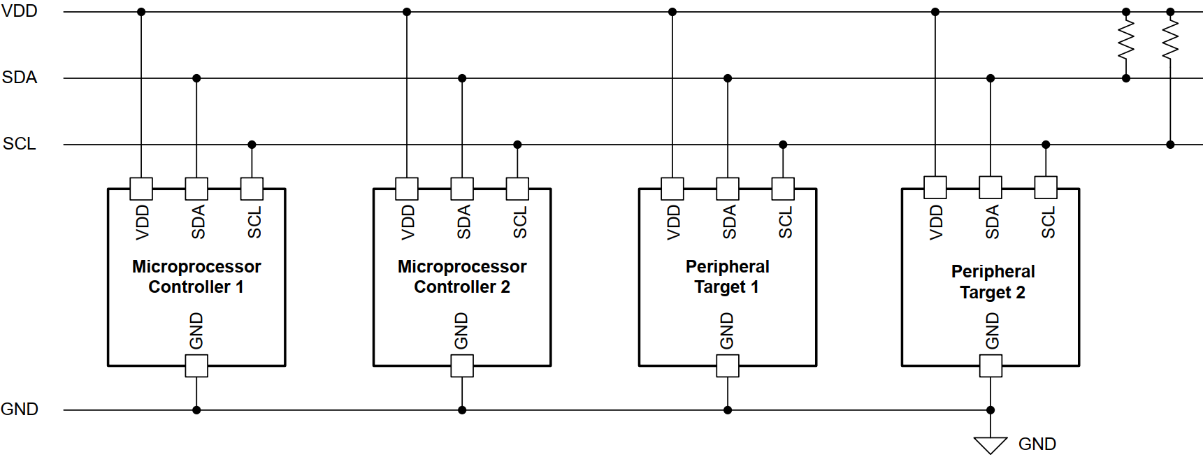
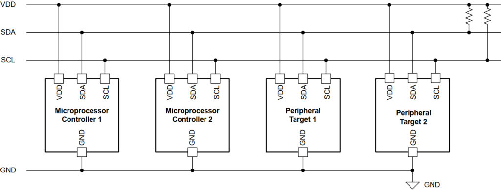
Inter-Integrated Circuit (I2C) is a synchronous, multi-device serial communication bus where a master controls all communication. The master initiates and completes transactions, sends an address frame to select a slave, and then transfers data. Communication uses two lines—SCL (clock) and SDA (data)—with data changing when SCL is low and being sampled when SCL is high.
Master Transmitter (MT) : master device initiates the transaction and sends data to a slave.
Master Receiver (MR): master device initiates the transaction and receives data from a slave.
Slave Transmitter (ST): slave device is addressed by the master and sends data to the master.
Slave Receiver (SR): slave device is addressed by the master and receives data from master.
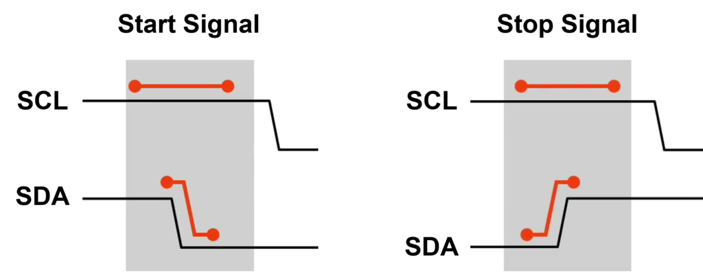
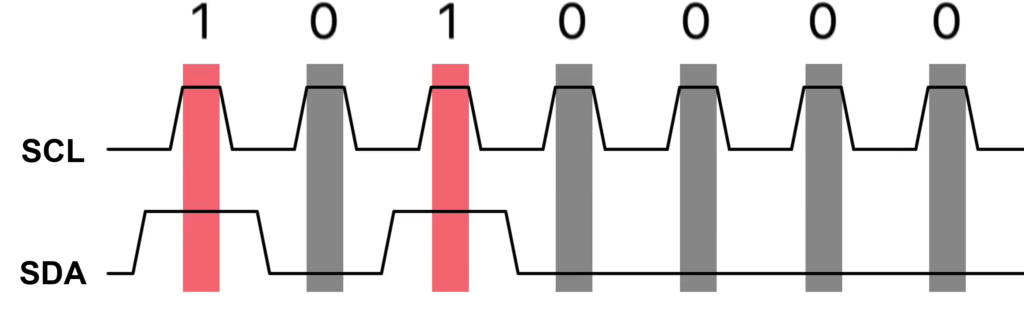
The START condition is formed when SDA transitions from high to low while SCL remains high, indicating the beginning of a transaction. Conversely, the STOP condition occurs when SDA transitions from low to high while SCL is high, signaling the end of communication.
A high SDA level during the SCL high period represents logic 1, while a low SDA level represents logic 0.
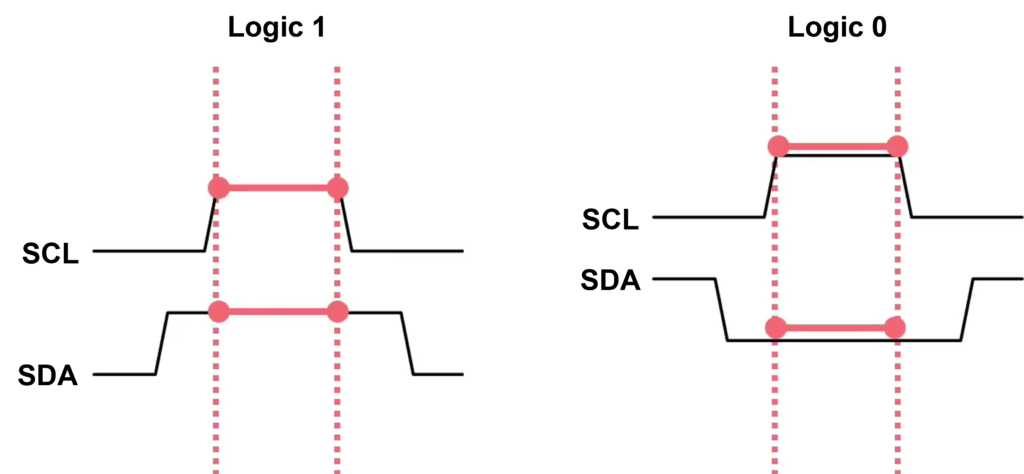
An example I2C data sequence, where multiple bits are clocked out synchronously with SCL. The highlighted regions emphasize that data is sampled on the rising or high phase of the clock, which is a key timing rule in I2C communication.
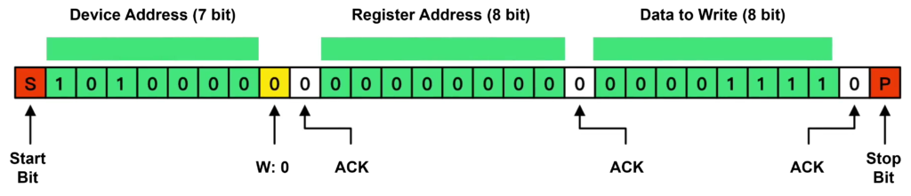
I2C Write Data
A master device sends data to a slave over the I2C bus using the SDA (data) and SCL (clock) lines.
- Start Condition (S): The Master pulls the SDA (data) line low while the SCL (clock) line is still high. This signals all devices on the bus to listen for an upcoming address.
- Addressing the Device: The Master sends a 7-bit Device Address to identify which slave it wants to talk to. A 0 (low) indicates a Write operation, while a 1 (high) would indicate a Read.
- Acknowledge (ACK): After every 8 bits of data, the receiving device must send an ACK bit. The slave pulls the SDA line low to say, “I received that byte.” In the diagram, these are the white boxes labeled ACK.
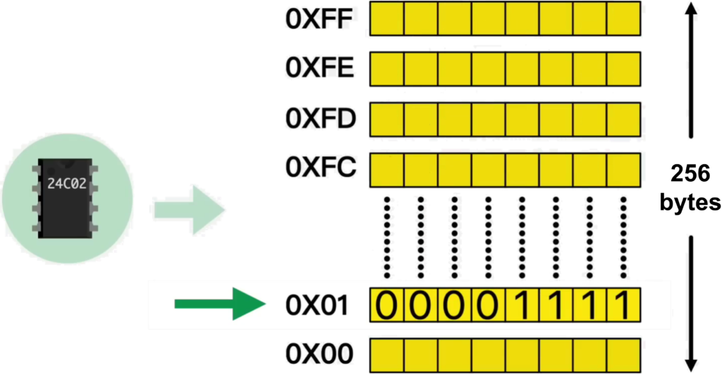
- Register Addressing: Once the device is selected, the Master sends the 8-bit Register Address. This tells the slave where inside its memory or internal settings the data should be written. The slave responds with another ACK.
- Data Transmission: The Master sends the actual data to write. The slave sends a final ACK to confirm the data was successfully received.
- Stop Condition (P): To finish the transaction, the Master issues a Stop Bit. It releases the SDA line (letting it go high) while the SCL line is high. This frees up the bus for other communications.
ACK (0, Low): The receiver has successfully received the byte and is pulling the SDA line down to signal the sender to continue.
ACK (1, High): The SDA line is left “high” (usually by the pull-up resistors). This signals that something went wrong or the transmission should end.
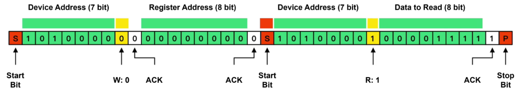
I2C Read Data
A master device requests and receives data from a slave device over the I2C bus using the SDA (data) and SCL (clock) lines.
Write Phase (Setting the Address)
- Start Condition (S): The Master pulls SDA low while SCL is high.
- Slave Address + Write (0): The Master sends the 7-bit Slave address followed by a 0 (Write bit) to indicate it is sending a command.
- Register Address: The Master sends the specific 8-bit memory address (Register) it wants to read from.
- Slave ACK: The Slave pulls SDA low after each byte to confirm receipt.
The Repeated Start: Instead of ending the communication with a “Stop” bit, the Master sends a Repeated Start. This allows the Master to keep control of the bus while switching from “Write Mode” to “Read Mode” without allowing other masters to interrupt.
Read Phase (Receiving Data)
- Slave Address + Read (1): The Master sends the Slave address again, but this time with the 8th bit set to 1 (Read).
- Data Frame: The Master stops driving the SDA line and starts providing clock pulses. The Slave takes control of SDA and sends the 8-bit data stored in the requested register.
- Master ACK/NACK: If the Master wants more bytes, it sends an ACK (0). If the Master is finished, it sends a NACK (1) to tell the Slave to stop sending data.
Stop Condition (P): The Master sends a Stop bit (SDA goes low-to-high while SCL is high) to release the bus.
[1] I2C通讯协议
[2] [Application Note] A Basic Guide to I2C
[3] [Application Note] Understanding the I2C Bus
[4] Basics of I2C: The I2C Protocol
Back to top of the page