
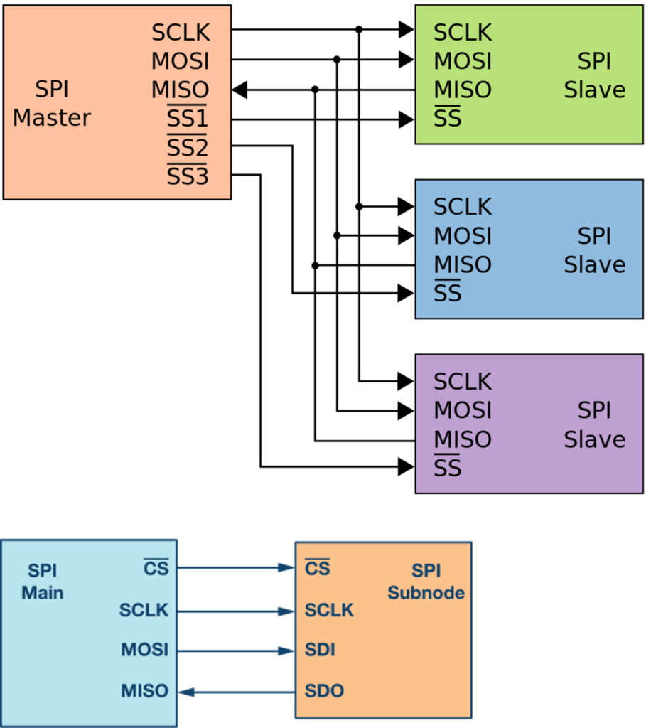
Serial Peripheral Interface (SPI) is a high-speed, synchronous serial communication protocol used primarily for short-distance communication between microcontrollers and peripheral devices (like sensors, SD cards, or displays).
MOSI: The data line for sending information from Master to Slave.
MISO: The data line for sending information from Slave back to Master.
SCLK: The clock signal generated by the controller to synchronize data.
CS/SS: Used by Master to “wake up” a specific Slave before talking to it.
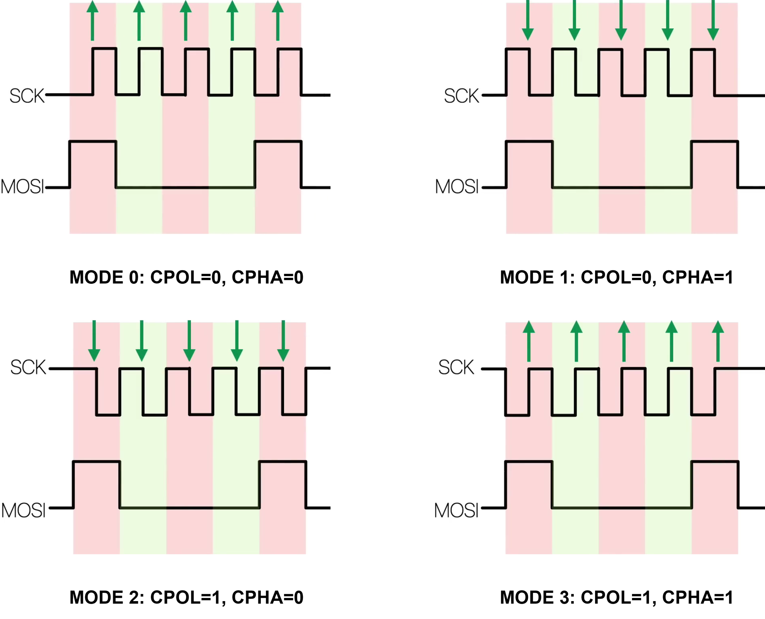
SPI Mode: The four SPI modes determine the clock edge on which data is sampled.
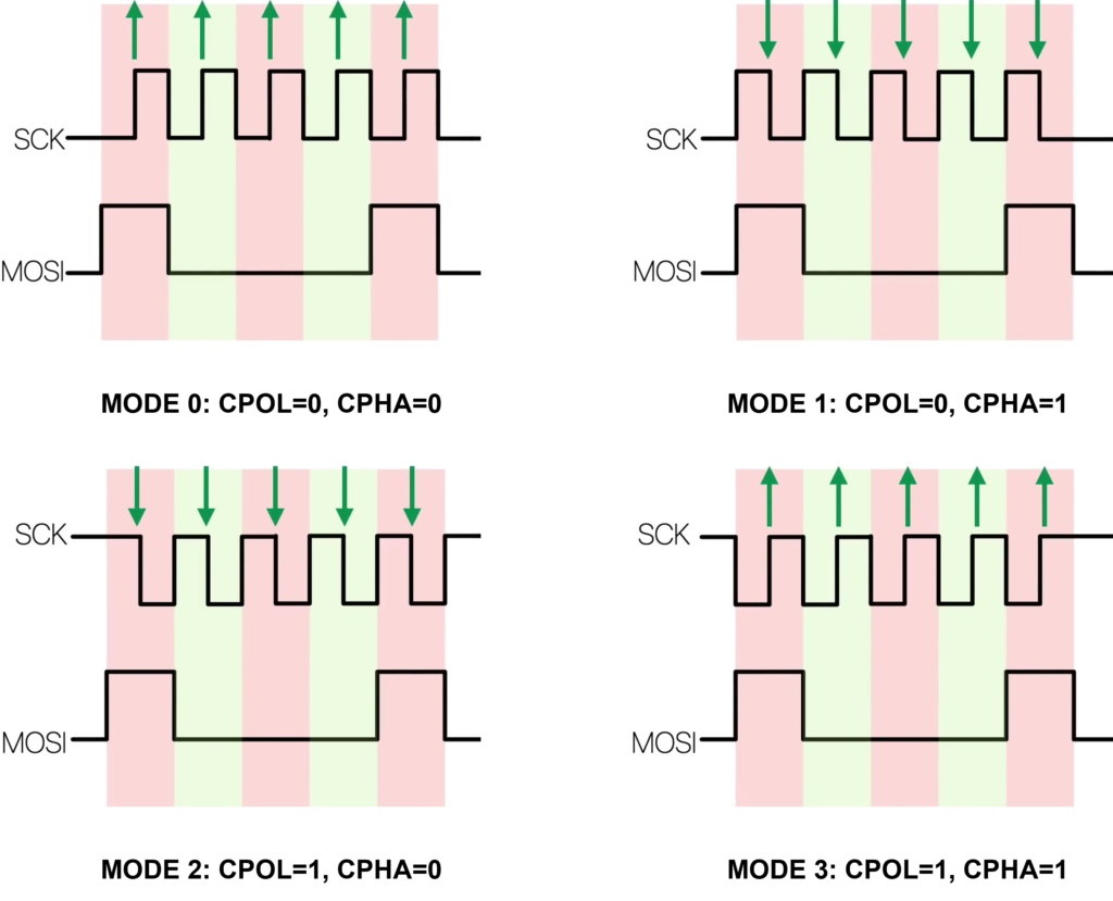
CPOL (Clock Polarity) – idle level of SCK
- CPOL = 0 → idle low
- CPOL = 1 → idle high
CPHA (Clock Phase) – sampling edge
- CPHA = 0 → first edge
- CPHA = 1 → second edge
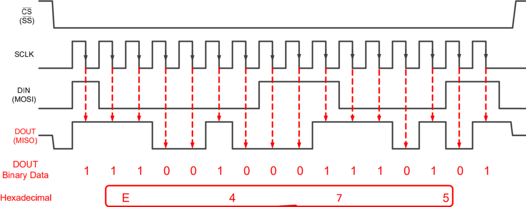
Green arrows indicate sampling edges (when data is read). MOSI data is expected to be stable at those arrows.
SPI Mode 0 (CPOL = 0, CPHA = 0)
- Clock idles low
- Data is sampled on the rising edge
- Data changes on the falling edge
SPI Mode 1 (CPOL = 0, CPHA = 1)
- Clock idles low
- Data is sampled on the falling edge
- Data changes on the rising edge
SPI Mode 2 (CPOL = 1, CPHA = 0)
- Clock idles high
- Data is sampled on the falling edge
- Data changes on the rising edge
SPI Mode 3 (CPOL = 1, CPHA = 1)
- Clock idles high
- Data is sampled on the rising edge
- Data changes on the falling edge
| SPI Mode | CPOL | CPHA | CLK Idle | Data Sampled On |
|---|---|---|---|---|
| Mode 0 | 0 | 0 | Low | Rising Edge |
| Mode 1 | 0 | 1 | Low | Falling Edge |
| Mode 2 | 1 | 0 | High | Falling Edge |
| Mode 3 | 1 | 1 | High | Rising Edge |
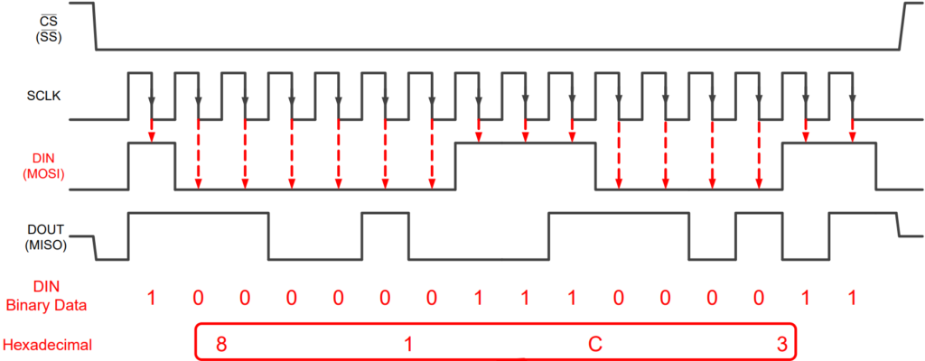
SPI Communication Example
Back to top of the page