
- Controller Area Network (CAN)
- CAN Termination
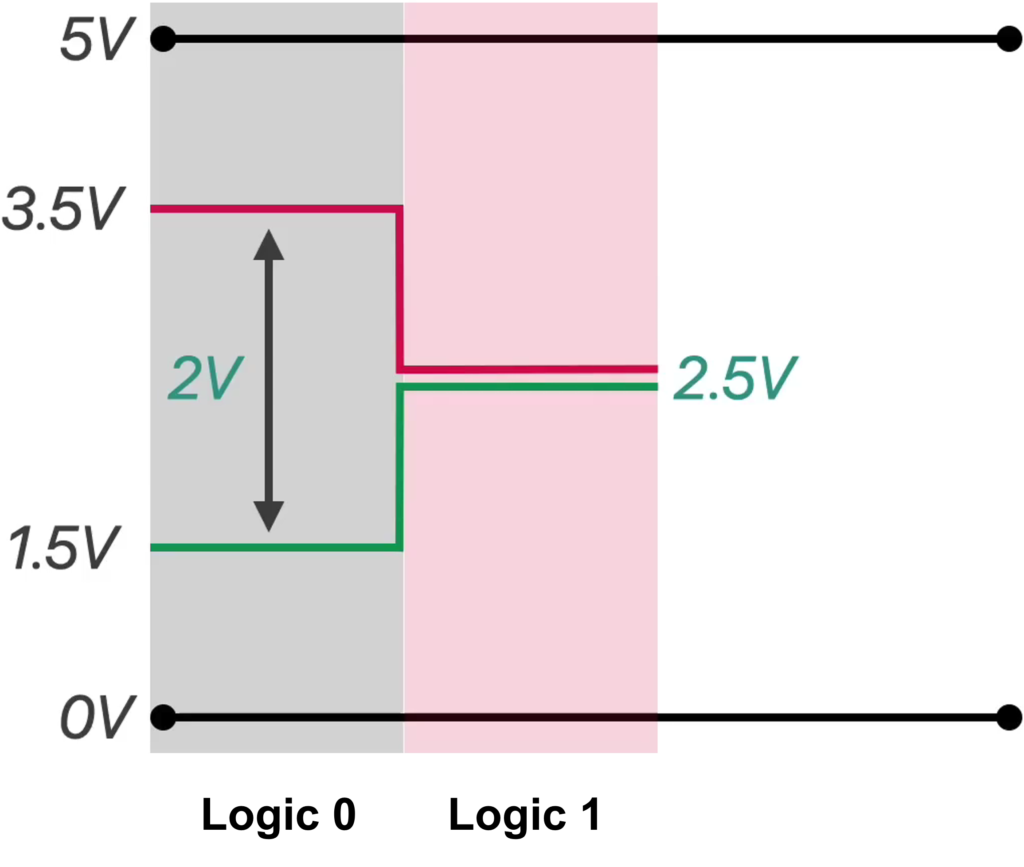
- CAN Logic Levels
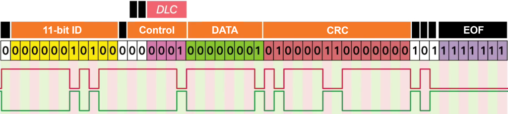
- CAN 2.0A Standard Frame
- CAN 2.0B Extended Frame
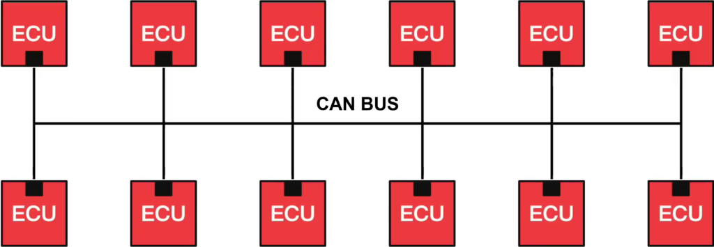
Controller Area Network (CAN) is a robust, message-based communication protocol designed to allow electronic control units (ECUs), sensors, and microcontrollers to communicate with each other reliably without the need for a central host computer.
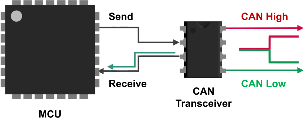
Wiring: Uses a twisted pair of wires (CAN High and CAN Low) to minimize interference.
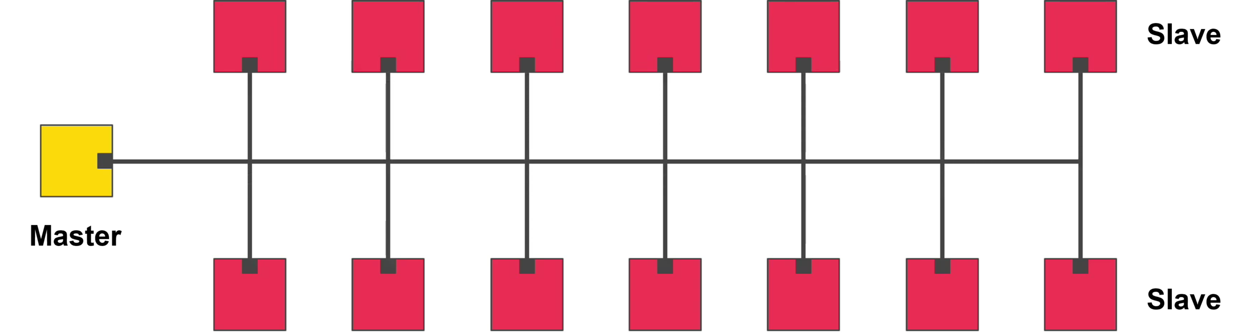
Topology: A decentralized “bus” where every device can see every message.
Arbitration: A priority-based system where lower ID numbers get the right of way.
Reliability: Includes automatic retransmission of failed messages and fault confinement.
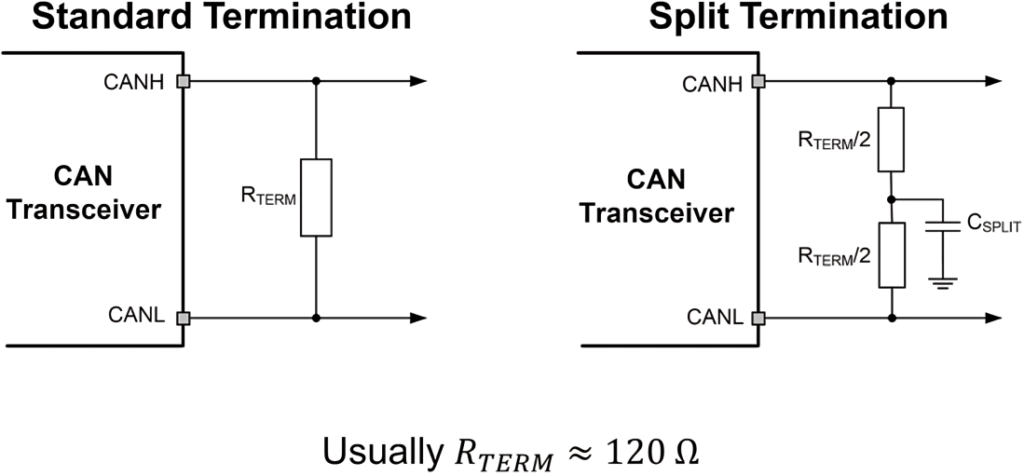
CAN Termination is critical for preventing signal reflections and ensuring the network remains stable.
CAN Logic Levels: CAN encodes bits using differential voltage: a dominant ‘0’ is created by driving CAN_H high and CAN_L low (~2 V difference), while a recessive ‘1’ leaves both lines at ~2.5 V (0 V difference), enabling robust noise immunity and bus arbitration.

CAN 2.0A Standard Frame

SOF (Start of Frame) – 1 bit
- Marks the beginning of a CAN frame
- Must be dominant (0) so every node can detect the frame start
Arbitration Field – 12 bits total
This decides which node wins if multiple ECUs transmit at the same time
11-bit Identifier (ID) – 11 bits
- The message name / priority number
- Lower numeric ID has higher priority on the CAN bus
RTR (Remote Transmission Request) – 1 bit
- 0 (dominant) = Data frame (normal frame carrying data)
- 1 (recessive) = Remote frame (requests data from another node)
Control Field – 6 bits total
Contains format and data length information
IDE / r1 – 1 bit
- In CAN 2.0A standard frame, IDE must be dominant (0), meaning 11-bit ID format
- Some diagrams label this bit as IDE, and also mention r1 (reserved usage)
r0 – 1 bit
- Reserved bit, must be dominant (0)
DLC (Data Length Code) – 4 bits
- 0 to 8 bytes in classic CAN
Data Field – 0 to 8 bytes
- The payload (actual content)
- Length is determined by DLC
CRC Field – 16 bits total
Used for error detection
CRC sequence – 15 bits
- CRC calculation result
CRC delimiter – 1 bit
- Must be recessive (1)
ACK Field – 2 bits total
Confirms that someone received the frame correctly
ACK slot – 1 bit
- Transmitter sends recessive (1)
- Any receiver that got the frame OK will overwrite it with dominant (0)
ACK delimiter – 1 bit
- Must be recessive (1)
EOF (End of Frame) – 7 bits
- Must be all recessive (1)
- Marks frame end and bus return to idle
CAN 2.0B Extended Frame

Arbitration Field (29-bit ID) – 32 bits total
This part is used for bus arbitration (priority) and message identification
11-bit Identifier (ID) – 11 bits
- The top 11 bits of the 29-bit identifier
SRR (Substitute Remote Request) – 1 bit
- Always recessive (1) in extended frames
IDE (Identifier Extension) – 1 bit
- IDE = 1 (recessive), this is an extended frame
18-bit Identifier (ID) – 18 bits
- Remaining 18 bits of the 29-bit identifier
RTR (Remote Transmission Request) – 1 bit
- 0 (dominant) = Data frame (normal frame carrying data)
- 1 (recessive) = Remote frame (requests data from another node)
Control Field – 6 bits total
Contains format and data length information
r1/r0 (reserved) – 1 bit
- Reserved bits must be dominant (0)
[1] CAN总线通讯协议
Back to top of the page