
- TMS320F28x7x Reset Sources
- TMS320F28x7x Dual-Core Boot Process
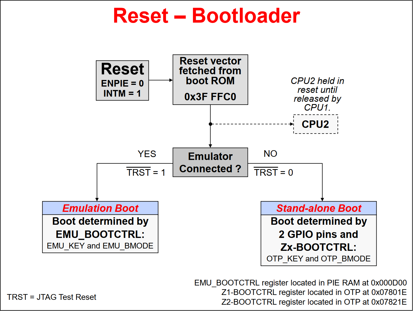
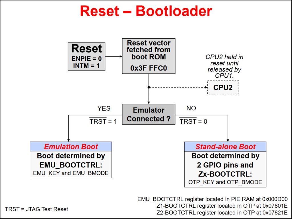
- TMS320F28x7x Reset – Bootloader
- TMS320F28x7x Emulation Boot Mode
- TMS320F28x7x Stand-Alone Boot Mode
- TMS320F28x7x Reset Code Flow
- TMS320F28x7x Emulation Boot Mode using GEL
- TMS320F28x7x main()
- TMS320F28x7x Peripheral Software Reset Registers
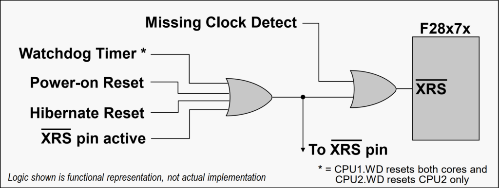
The device has various reset sources, but in general resets on CPU1 will reset the entire device and resets on CPU2 will reset only the CPU2 subsystem. The reset sources include an external reset pin, watchdog timer reset, power-on reset which generates a device reset during power-up conditions, Hibernate reset, as well as a missing clock detect reset. A reset cause register (RESC) is available for each CPU subsystem which can be read to determine the cause of the reset. The external reset pin is the main chip-level reset for the device, and it resets both CPU subsystems to their default state. The power-on reset (POR) circuit is used to create a clean reset throughout the device during power-up, while suppressing glitches on the input/output pins.
- CPU1 starts execution from CPU1 boot ROM while CPU2 is held in reset
- CPU1 controls the boot process
- CPU2 goes through its own boot process under the control of CPU1 – except when CPU2 is set to boot-to-flash
- IPC registers are used to communicate between CPU1 and CPU2 during the boot process
During the F2837xD dual-core microcontroller booting, CPU1 controls the boot process and starts execution from the CPU1 boot ROM while CPU2 is held in reset. CPU2 goes through its own boot process under the control of CPU1, except when CPU2 is set to boot-to-flash. The IPC registers are used to communicate between CPU1 and CPU2 during the boot process. Additionally, the boot ROM contains the necessary boot loading routines to support peripheral boot loading.
When the device is reset, the peripheral interrupt expansion block, also known as the PIE block, and the master interrupt switch INTM are disabled. This prevents any interrupts during the boot process. The program counter is set to 0x3FFFC0, where the reset vector is fetched. In the boot code the JTAG Test Reset line (TRST line) is checked to determine if the emulator is connected.
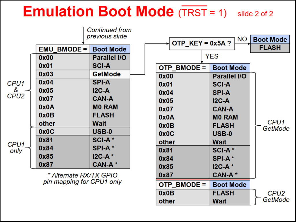
If the emulator is connected, then the boot process follows the Emulation Boot mode flow. In Emulation Boot mode, the boot is determined by the EMU_BOOTCTRL register located in the PIE RAM. Specific details about the boot flow are then determined by the EMU_KEY and EMU_BMODE bit fields in the EMU_BOOTCTRL register.
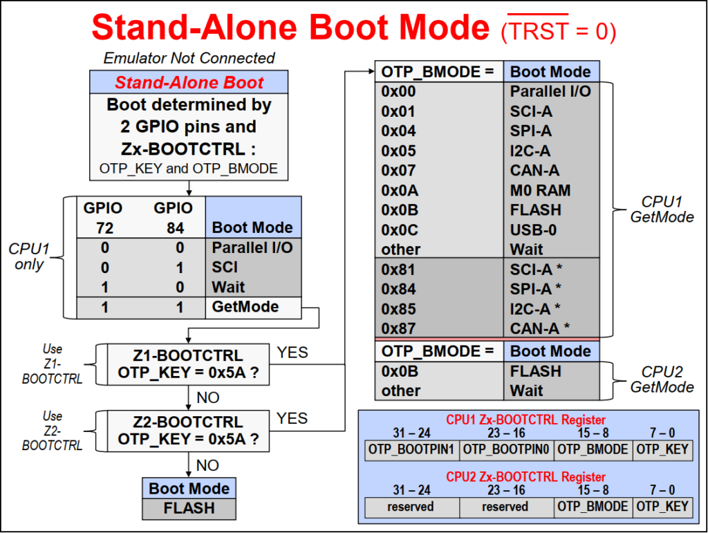
If the emulator is not connected, the boot process follows the Stand-alone Boot mode flow. In Stand-alone Boot mode, the boot is determined by two GPIO pins and the Z1-BOOTCTRL and Z2-BOOTCTRL registers located in the OTP. Specific details about the boot flow are then determined by the OTP_KEY and OTP_BMODE bit fields in the Z1-BOOTCTRL and Z2-BOOTCTRL registers
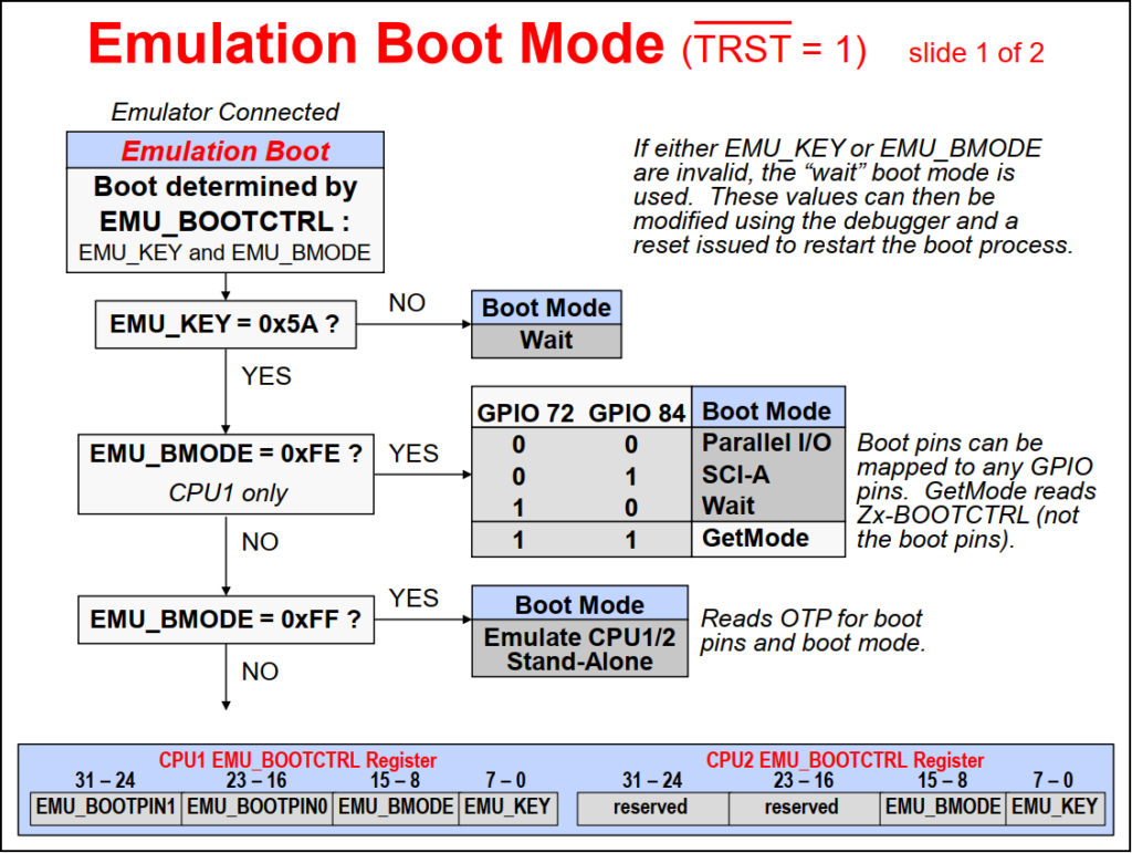
In Emulation Boot mode, first the EMU_KEY bit fields are checked for a value of 0x5A. If either EMU_KEY or EMU_BMODE bit fields are invalid, the “Wait” boot mode is entered. These bit field values can then be modified using the debugger and then a reset is issued to restart the boot process. This is the typical sequence followed during device power-up with the emulator connected, allowing the user to control the boot process using the debugger.
Once the EMU_KEY bit fields are set to 0x5A, then the EMU_BMODE bit field values determines the boot mode. The various Emulation Boot modes supported are Parallel I/O, SCI, SPI, I2C, CAN, M0 RAM, FLASH, USB, and Wait. The GetMode and when EMU_BMODE bit fields have a value of 0xFE or 0xFF are used to emulate the Stand-alone Boot mode.
In Stand-alone boot mode, first GPIO pins 72 and 84 are checked to determine if the boot mode is Parallel I/O, SCI, Wait, or GetMode. These pin can be remapped to any GPIO pins, if needed, and the default “unconnected” pins set the boot mode to GetMode. In GetMode the OTP_KEY bit fields in the Z1-BOOTCTRL and Z2-BOOTCTRL registers are checked for a value of 0x5A. An un-programmed device will have these locations set as 1’s, and the flash boot mode is entered, as expected for the default mode. If the OTP_KEY bit fields in either Z1-BOOTCTRL or Z2-BOOTCTRL registers has a value of 0x5A, then the OTP_BMODE bit field values in the registers determines the boot mode. The various Stand-alone Boot modes supported are Parallel I/O, SCI, SPI, I2C, CAN, M0 RAM, FLASH, USB, and Wait.
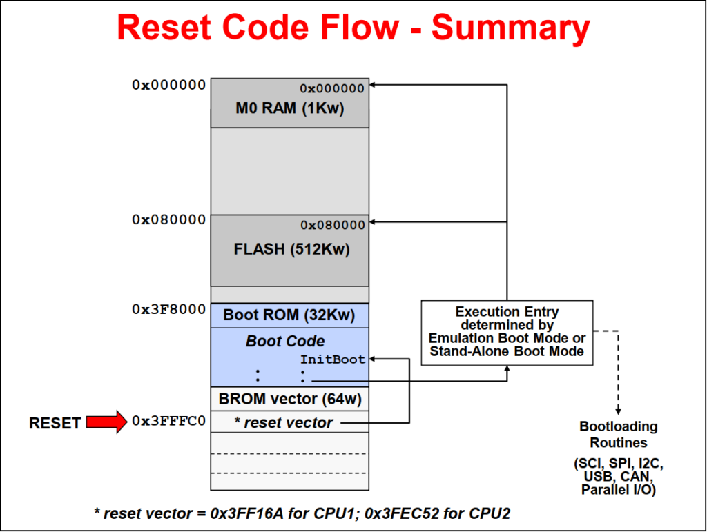
The reset code flow is as follows. After reset, the program counter is set to 0x3FFFC0, where the flow is vectored to the Init_Boot code in the Boot ROM. The Init_Boot code defines the execution entry based on emulation boot mode or stand-alone boot mode. The entry point can be executing boot-loading routines, entry to the flash, or M0 RAM.
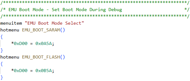
The CCS GEL file is used to setup the boot modes for the device during debug. By default the GEL file provides functions to set the device for Boot to SARAM and Boot to FLASH. It can be modified to include other boot mode options, if desired.
To access the GEL file use: Views -> GEL Files
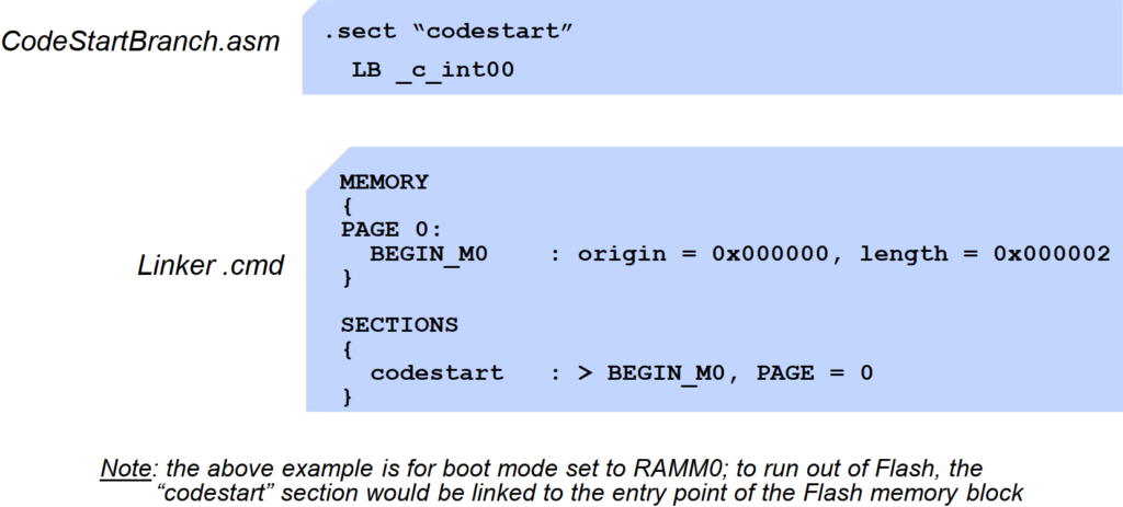
When the bootloader process is completed, a branch to the compiler runtime support library is located at the code entry point. This branch to _c_int00 is executed, then the compiler environment is set up, and finally main is called.
At the code entry point, branch to _c_int00()
- Part of compiler runtime support library
- Sets up compiler environment
- Calls main()
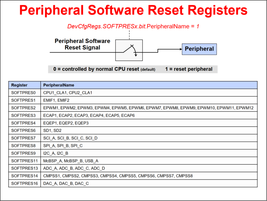
The peripheral software reset register contains the reset bit for each peripheral.
Back to top of the page