
Please also see this post about the SCI/UART communication protocol.
- TMS320F28x7x Serial Communications Interface (SCI)
- TMS320F28x7x SCI Multiprocessor Wake-Up Modes
- TMS320F28x7x SCI Summary
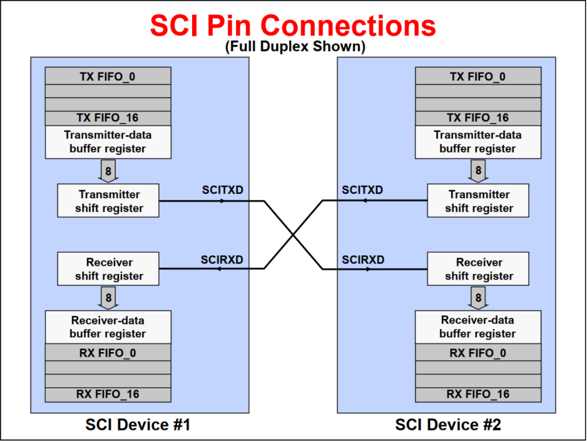
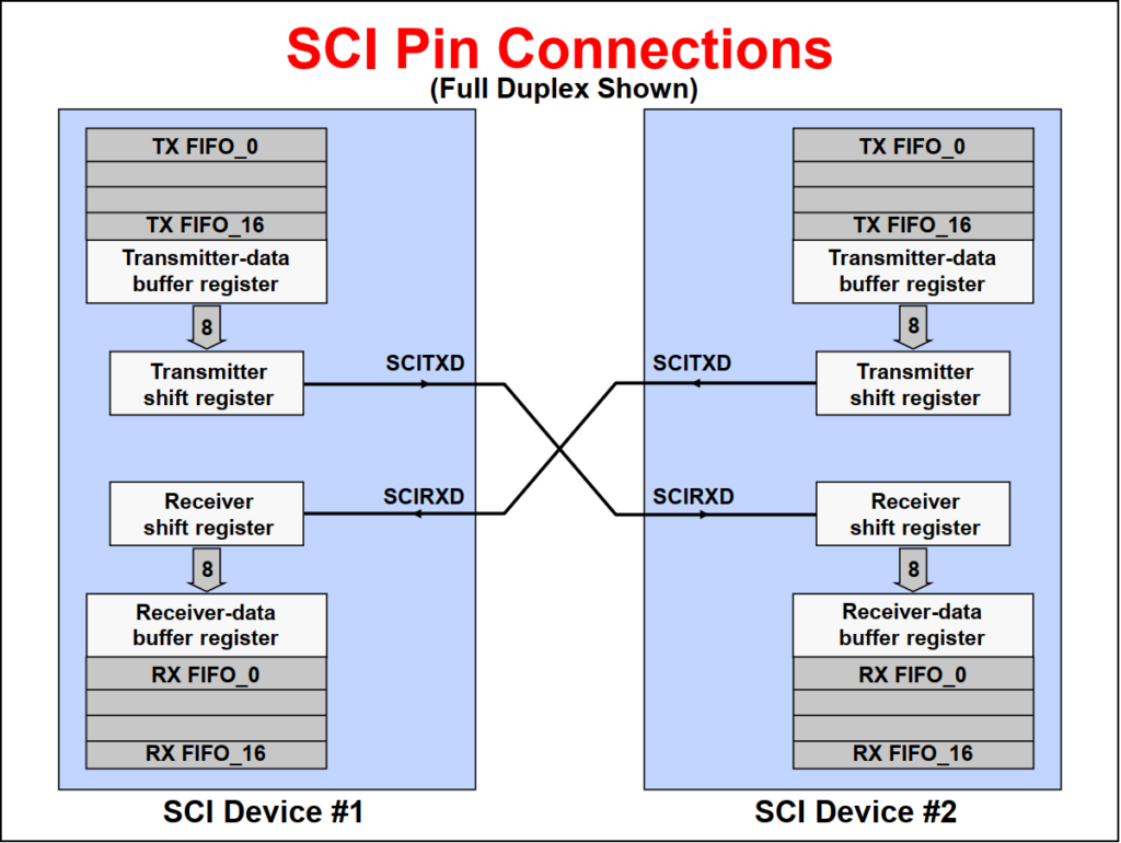
The SCI is a two-wire asynchronous serial port (also known as a UART) that supports communications between the processor and other asynchronous peripherals that use the standard non-return-to-zero (NRZ) format. A receiver and transmitter 16-level deep FIFO is used to reduce servicing overhead. The SCI transmit and receive registers are both double-buffered to prevent data collisions and allow for efficient CPU usage. In addition, the C28x SCI is a full duplex interface which provides for simultaneous data transmit and receive. Parity checking and data formatting is also designed to be done by the port hardware, further reducing software overhead.
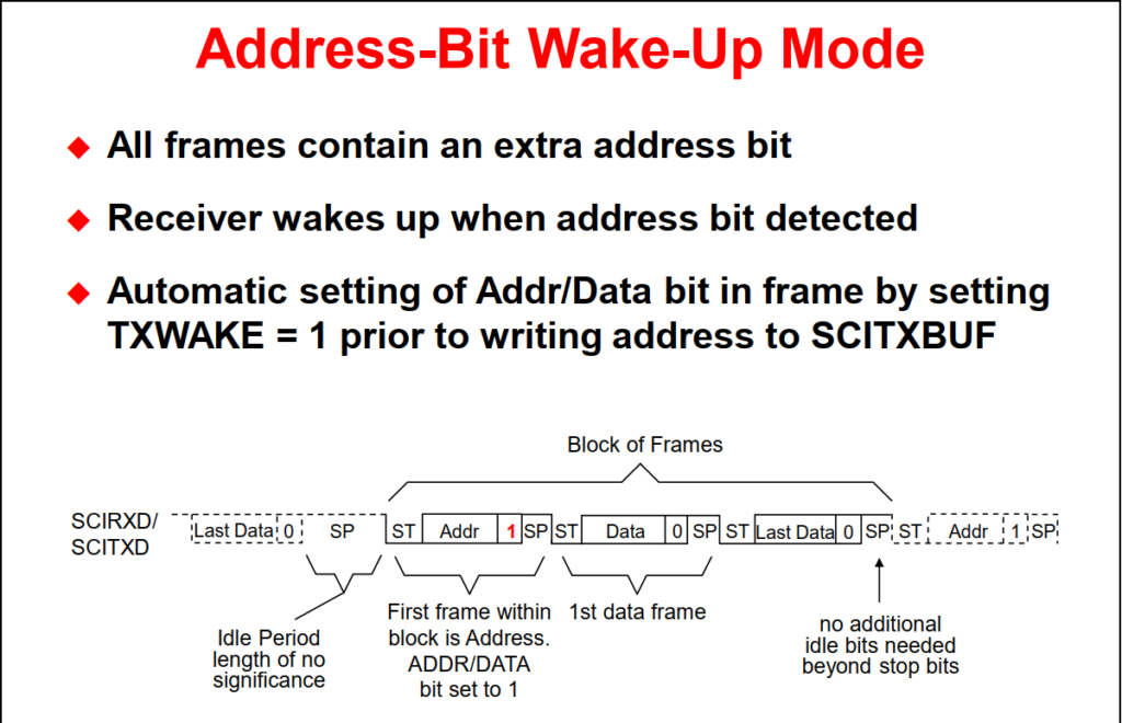
The basic unit of data is called a character and is 1 to 8 bits in length. Each character of data is formatted with a start bit, 1 or 2 stop bits, an optional parity bit, and an optional address/data bit. A character of data along with its formatting bits is called a frame. Frames are organized into groups called blocks. If more than two serial ports exist on the SCI bus, a block of data will usually begin with an address frame which specifies the destination port of the data as determined by the user’s protocol.
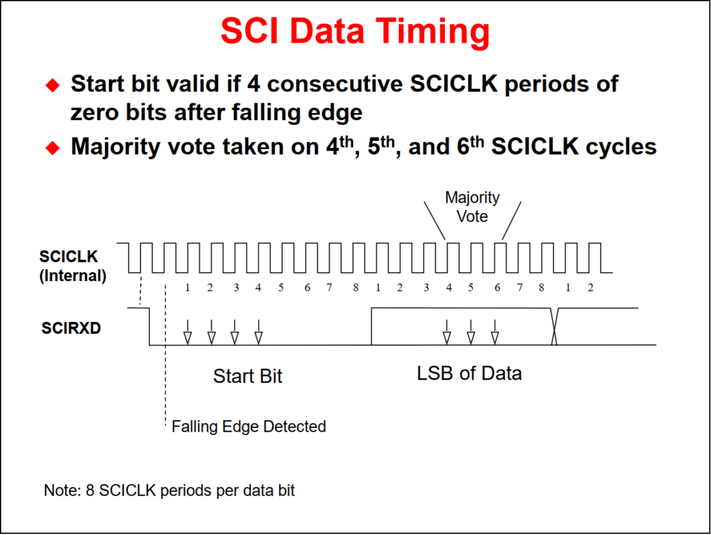
The start bit is a low bit at the beginning of each frame which marks the beginning of a frame. The SCI uses a NRZ (Non-Return-to-Zero) format which means that in an inactive state the SCIRX and SCITX lines will be held high. Peripherals are expected to pull the SCIRX and SCITX lines to a high level when they are not receiving or transmitting on their respective lines.
When configuring the SCICCR, the SCI port should first be held in an inactive state. This is done using the SW RESET bit of the SCI Control Register 1 (SCICTL1.5). Writing a 0 to this bit initializes and holds the SCI state machines and operating flags at their reset condition. The SCICCR can then be configured. Afterwards, re-enable the SCI port by writing a 1 to the SW RESET bit. At system reset, the SW RESET bit equals 0.
- Allows numerous processors to be hooked up to the bus, but transmission occurs between only two of them
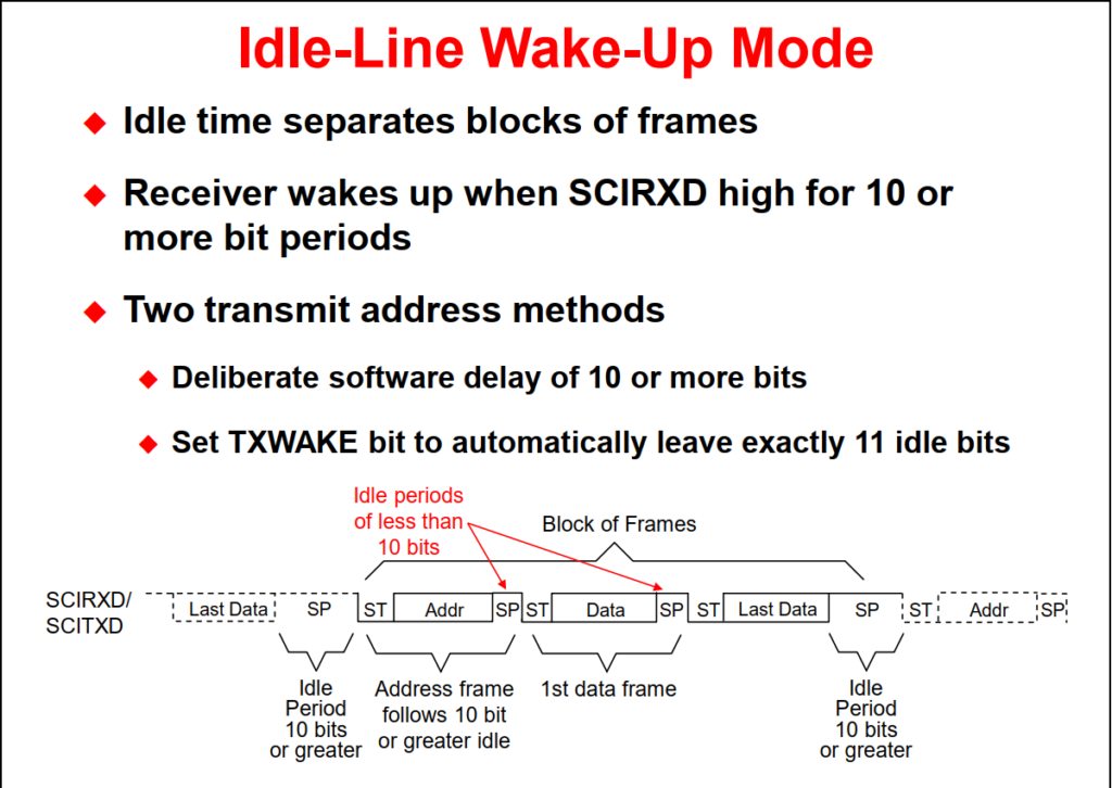
- Idle-line or Address-bit modes
-
Sequence of Operation
- Potential receivers set SLEEP = 1, which disables RXINT except when an address frame is received
- All transmissions begin with an address frame
- Incoming address frame temporarily wakes up all SCIs on bus
- CPUs compare incoming SCI address to their SCI address
- Process following data frames only if address matches
The SCI interrupt logic generates interrupt flags when it receives or transmits a complete character as determined by the SCI character length. This provides a convenient and efficient way of timing and controlling the operation of the SCI transmitter and receiver. The interrupt flag for the transmitter is TXRDY (SCICTL2.7), and for the receiver RXRDY (SCIRXST.6). TXRDY is set when a character is transferred to TXSHF and SCITXBUF is ready to receive the next character. In addition, when both the SCIBUF and TXSHF registers are empty, the TX EMPTY flag (SCICTL2.6) is set. When a new character has been received and shifted into SCIRXBUF, the RXRDY flag is set. In addition, the BRKDT flag is set if a break condition occurs. A break condition is where the SCIRXD line remains continuously low for at least ten bits, beginning after a missing stop bit. Each of the above flags can be polled by the CPU to control SCI operations, or interrupts associated with the flags can be enabled by setting the RX/BK INT ENA (SCICTL2.1) and/or the TX INT ENA (SCICTL2.0) bits active high.
Additional flag and interrupt capability exists for other receiver errors. The RX ERROR flag is the logical OR of the break detect (BRKDT), framing error (FE), receiver overrun (OE), and parity error (PE) bits. RX ERROR high indicates that at least one of these four errors has occurred during transmission. This will also send an interrupt request to the CPU if the RX ERR INT ENA (SCICTL1.6) bit is set.
- Asynchronous communications format
- 65,000+ different programmable baud rates
- Two wake-up multiprocessor modes
- Idle-line wake-up & Address-bit wake-up
- Programmable data word format
- 1 to 8 bit data word length
- 1 or 2 stop bits
- even/odd/no parity
- Error Detection Flags
- Parity error; Framing error; Overrun error; Break detection
- Transmit FIFO and receive FIFO
- Individual interrupts for transmit and receive
Back to top of the page