
Please also see this post about the CAN communication protocol.
- TMS320F28x7x Controller Area Network (CAN)
- TMS320F28x7x CAN Bus and Node
- TMS320F28x7x Principles of Operation
- TMS320F28x7x Message Format and Block Diagram
- TMS320F28x7x CAN Summary
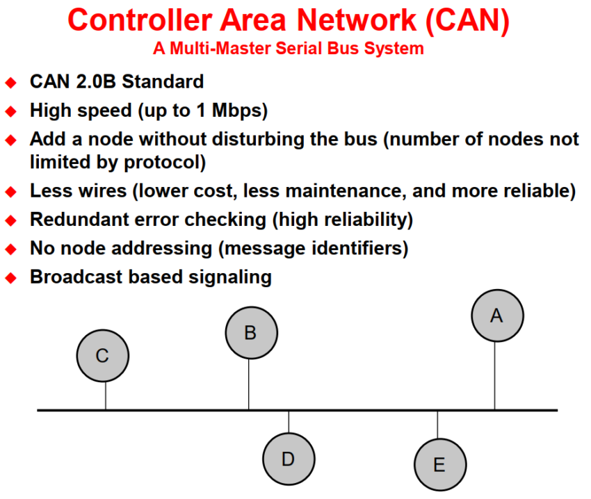
The CAN module is a serial communications protocol that efficiently supports distributed real-time control with a high level of security. It supports bit-rates up to 1 Mbit/s and is compliant with the CAN 2.0B protocol specification.
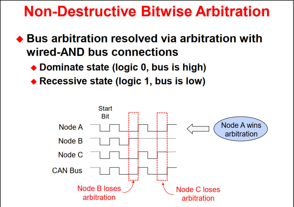
CAN does not use physical addresses to address stations. Each message is sent with an identifier that is recognized by the different nodes. The identifier has two functions – it is used for message filtering and for message priority. The identifier determines if a transmitted message will be received by CAN modules and determines the priority of the message when two or more nodes want to transmit at the same time.

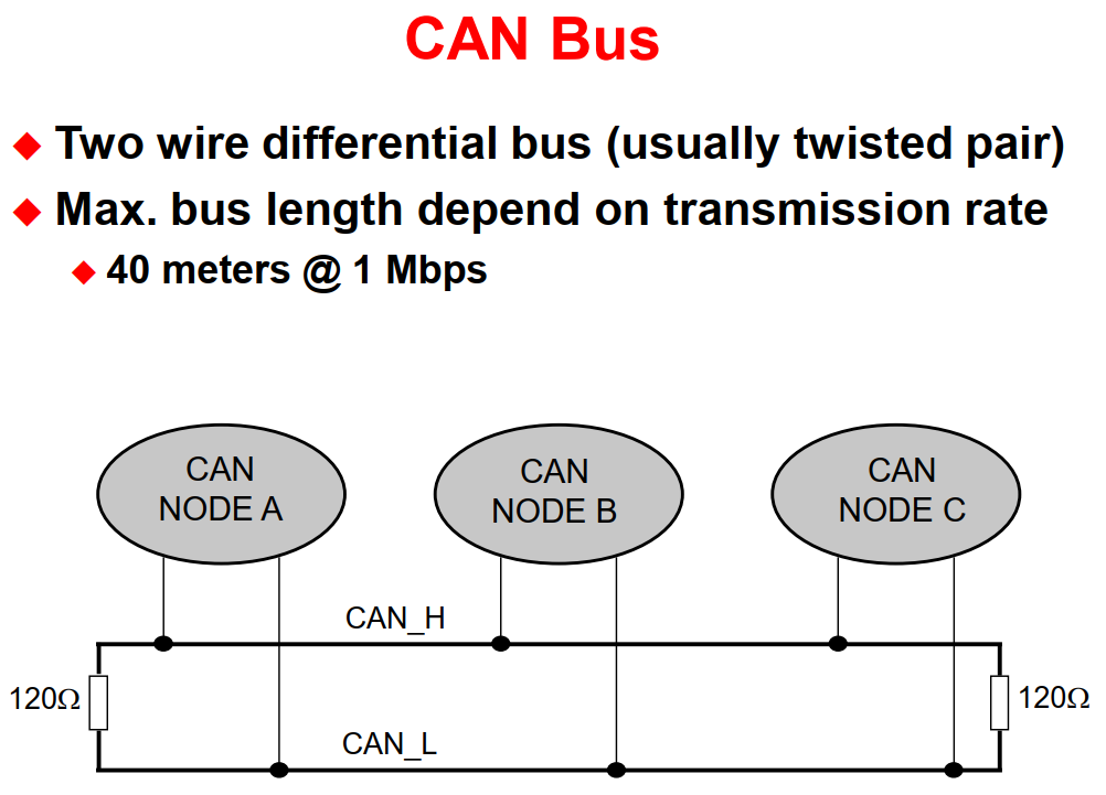
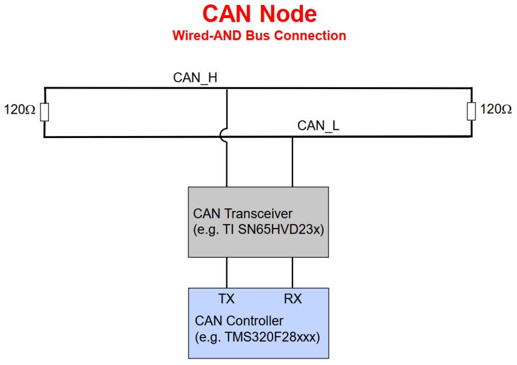
The MCU communicates to the CAN Bus using a transceiver. The CAN bus is a twisted pair wire and the transmission rate depends on the bus length. If the bus is less than 40 meters the transmission rate is capable up to 1 Mbit/second.
- Data messages transmitted are identifier based, not address based
- Content of message is labeled by an identifier that is unique throughout the network
- (e.g. rpm, temperature, position, pressure, etc.)
- All nodes on network receive the message and each performs an acceptance test on the identifier
- If message is relevant, it is processed (received); otherwise it is ignored
- Unique identifier also determines the priority of the message
- (lower the numerical value of the identifier, the higher the priority)
- When two or more nodes attempt to transmit at the same time, a non-destructive arbitration technique guarantees messages are sent in order of priority and no messages are lost
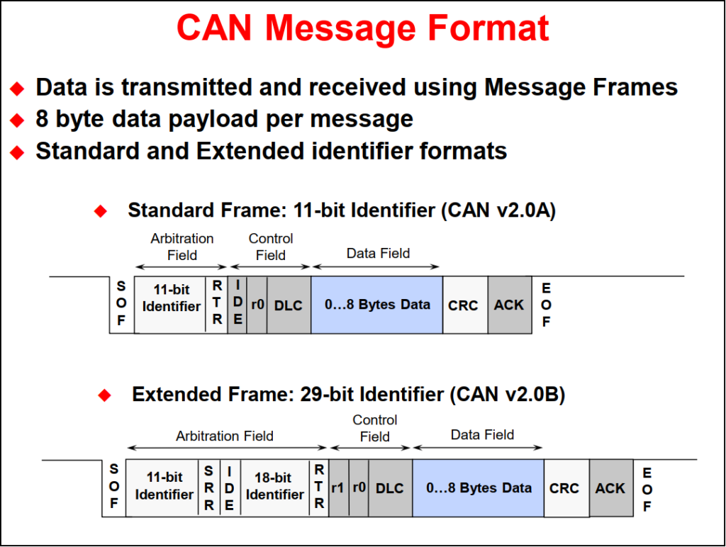
The MCU CAN module is a full CAN Controller. It contains a message handler for transmission and reception management, and frame storage. The specification is CAN 2.0B Active – that is, the module can send and accept standard (11-bit identifier) and extended frames (29-bit identifier).
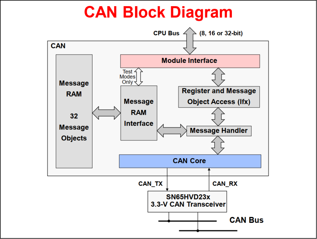
The CAN controller module contains 32 mailboxes for objects of 0 to 8-byte data lengths:
- configurable transmit/receive mailboxes
- configurable with standard or extended indentifier
The CAN module mailboxes are divided into several parts:
- MID – contains the identifier of the mailbox
- MCF (Message Control Field) – contains the length of the message (to transmit or receive) and the RTR bit (Remote Transmission Request – used to send remote frames)
- MDL and MDH – contains the data
The CAN module contains registers which are divided into five groups:
- Control & Status Registers
- Local Acceptance Masks
- Message Object Time Stamps
- Message Object Timeout
- Mailboxes
- Fully compliant with CAN standard v2.0B
- Supports data rates up to 1 Mbps
- Thirty-two message objects
- Configurable as receive or transmit
- Configurable with standard or extended identifier
- Programmable receive mask
- Uses 32-bit time stamp on messages
- Programmable interrupt scheme (two levels)
- Programmable alarm time-out
- Programmable wake-up on bus activity
- Two interrupt lines
- Self-test mode
Back to top of the page