
- Zephyr Devicetree
- Devicetree Overlays
- Devicetree Build Flow
- Modifying Devicetree Nodes with Overlays
- Zephyr Devicetree Structure: ADC Configuration Example
Zephyr uses devicetree to describe hardware separately from application logic. Peripheral addresses, interrupt numbers, pin assignments, and other hardware-specific details are defined at build time rather than hardcoded in source code.
The devicetree is then processed into compile-time information that drivers and applications can access through generated macros. This separation improves portability and maintainability, allowing the same application code to run on different boards and SoCs while board-specific hardware configuration is selected during the build process.
With devicetree, each vendor describes hardware in its own .dts file. The hardware description differs, but the application code does not change time. This approach is lightweight and efficient for embedded systems.
# Vendor A
uart0: uart@40021000 {
  compatible = "vendora,uart";
  reg = <0x40021000 0x400>;
  status = "okay";
};

# Vendor B
uart0: uart@50003000 {
  compatible = "vendorb,uart";
  reg = <0x50003000 0x400>;
  status = "okay";
};A Zephyr board typically does not describe all hardware in a single .dts file.
The main board devicetree file:
zephyr/boards/<vendor>/<board>/<board>.dts
usually includes one or more .dtsi files that provide shared hardware descriptions, such as:
- SoC configuration
- Pin control definitions
- Shared peripherals
- Common board-level hardware features
This generated file represents the final hardware description used by the build system and is useful for verifying the effective configuration and debugging devicetree-related issues.
Board devicetree files define the default hardware configuration for a board. However, applications often need to enable additional peripherals, modify existing properties, or describe application-specific hardware without changing the original board files. Devicetree overlays provide a flexible way to extend or override the board’s default hardware configuration at build time while keeping the base board definition unchanged.
Alternatively, an app.overlay file can be created in the application root directory. If both app.overlay and boards/<board_name>.overlay are present, Zephyr uses the board-specific overlay for the selected board.
└── apps/
      └── project
             ├── CMakeLists.txt
             ├── Kconfig
             ├── prj.conf
             ├── extra.conf
             ├── app.overlay
             └── boards/
                  ├── <board_name>.conf
                  └── <board_name>.overlay
             └── src/
└── main.c# app.overlay
&i2c1 {
status = "okay";
mpu6050: mpu6050@68 {
compatible = "invensense,mpu6050";
reg = <0x68>;
};
};
# boards/stm32f4_disco.overlay
/ {
aliases {
led0 = &red_led_5;
led1 = &blue_led_6;
led2 = &green_led_4;
led3 = &orange_led_3;
sw0 = &user_button;
};
};
&adc1{
pinctrl-0 = <&adc1_in1_pa1>;
pinctrl-names = "default";
st,adc-prescaler = <4>;
status = "okay";
};Devicetree overlays do not replace the board’s devicetree source file. Instead, they are merged with the base devicetree to extend or override its configuration.
Because overlays are applied during the build process, they can:
- Override existing property values
- Change a node’s status
- Add new nodes or properties
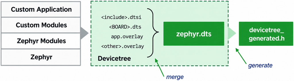
The build process is:
- Devicetree source files and overlays are merged into a single hardware description
- The merged result is written to zephyr.dts
- Zephyr generates devicetree_generated.h from the final devicetree
The devicetree_generated.h file contains C macros generated from the final merged devicetree. These macros are automatically made available to the application and drivers during compilation.
They allow source code to:
- Reference devicetree nodes
- Read properties defined in the devicetree
- Check whether a node or device is enabled
- Access hardware information such as addresses, interrupts, GPIOs, and other configuration data
└── build/project/zephyr/
      ├── zephyr.dts (merged Devicetree output)
      └── include/generated/zephyr/
└── devicetree_generated.h (Devicetree macros)Board devicetree files define the default hardware configuration for most peripherals and devices. However, applications often need to enable a disabled peripheral, modify an existing property, or add application-specific hardware settings without changing the original board definition. Devicetree overlays provide a clean way to extend or override only the required parts of the hardware description.
# stm32f4.dtsi
adc1: adc@40012000 {
compatible = "st,stm32f4-adc", "st,stm32-adc";
reg = <0x40012000 0x400>;
clocks = <&rcc STM32_CLOCK(APB2, 8)>;
clock-names = "adcx";
interrupts = <18 0>;
#io-channel-cells = <1>;
st,adc-resolutions = <12 10 8 6>;
sampling-times = <3 15 28 56 84 112 144 480>;
st,adc-clock-source = "SYNC";
st,adc-sequencer = "programmable";
st,adc-oversampler = "none";
st,adc-internal-regulator = "none";
st,adc-has-injected-support;
status = "disabled";
};
# stm32f4_disco.dts
&adc1 {
pinctrl-0 = <&adc1_in1_pa1 &adc1_in6_pa6>;
pinctrl-names = "default"; # Index 0 corresponds to "default"
st,adc-prescaler = <2>;
status = "okay"; # Enable this hardware peripheral for use by Zephyr
};Enable STM32 ADC1, configure PA1 as ADC1 channel 1 and PA6 as ADC1 channel 6, use these pins as ADC1’s default pin configuration, and configure the STM32-specific ADC clock prescaler.
pinctrl-0 = <&adc1_in1_pa1 &adc1_in6_pa6>;
# PA1 -> ADC1_IN1
adc1_in1_pa1
│ │
│ └── PA1
└────── ADC1 input channel 1
# PA6 -> ADC1_IN6
adc1_in6_pa6
│ │
│ └── PA6
└────── ADC1 input channel 6 boards/stm32f4_disco.overlay
This overlay modifies the existing adc1 node for the stm32f4_disco board and then defines one ADC channel configuration for the application.
&adc1 {
# Overrides the board's default pinctrl list
pinctrl-0 = <&adc1_in1_pa1>;
# Reconfigures an ST-specific ADC clock prescaler
st,adc-prescaler = <4>;
# Enables ADC1
status = "okay";
# Creates a child node describing an ADC channel configuration
channel@1 {
reg = <1>; # ADC channel 3
# Sets the ADC gain to 1
zephyr,gain = "ADC_GAIN_1";
# Selects the ADC reference configuration used by Zephyr
zephyr,reference = "ADC_REF_INTERNAL";
# Sets the ADC sample/acquisition time
zephyr,acquisition-time = <ADC_ACQ_TIME_DEFAULT>;
# Perform the ADC conversion using 12-bit resolution
zephyr,resolution = <12>;
};
};Perform a pristine rebuild and inspect zephyr.dts
└── build/project/zephyr/
      ├── zephyr.dts (merged Devicetree output)
      └── include/generated/zephyr/
              └── devicetree_generated.h (Devicetree macros)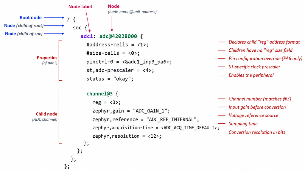
- adc1 is the node label. It allows references using &adc1
- adc@42028000 is the node name and unit address
Back to top of the page