
- Accessing GPIO using the Device Driver Model
- Accessing ADC Hardware through the Device Driver Model
- Creating a Custom Devicetree Binding
Zephyr applications typically interact with hardware through standardized subsystem APIs rather than accessing registers directly or relying on vendor-specific hardware abstraction layers (HALs). This hardware abstraction is provided by Zephyr’s device driver model and devicetree system: devicetree describes the hardware independently of the application, while the build system selects and configures the appropriate drivers automatically.
The code below uses Zephyr’s Device Driver Model and Devicetree to access a GPIO LED and push button. GPIO_DT_SPEC_GET() reads the GPIO controller, pin number, and configuration flags from the Devicetree aliases led0 and sw0, then stores that information in gpio_dt_spec structures. This lets the application work with GPIO hardware without hard-coding port and pin values, making the code more portable across different Zephyr-supported boards.
#include <zephyr/kernel.h>
#include <zephyr/drivers/gpio.h>

// prj.conf -> CONFIG_GPIO=y
//          -> CONFIG_PRINTK=y

const struct gpio_dt_spec led =
    GPIO_DT_SPEC_GET(DT_ALIAS(led0), gpios);

static const struct gpio_dt_spec button =
GPIO_DT_SPEC_GET(DT_ALIAS(sw0), gpios); The code below defines a GPIO interrupt callback for the push button. When the button generates an interrupt, button_isr() is called. The unused callback parameters are explicitly ignored with ARG_UNUSED(), while gpio_pin_get_dt() reads the current button state and prints whether it is active. Each interrupt also toggles the led_on variable and updates the LED through gpio_pin_set_dt(), demonstrating how Zephyr’s GPIO driver API can handle both GPIO input interrupts and GPIO output control through Devicetree-defined devices.
bool led_on;
static struct gpio_callback button_cb;

static void button_isr(const struct device *port,
                       struct gpio_callback *cb,
                       gpio_port_pins_t pins) {
    ARG_UNUSED(port);
    ARG_UNUSED(pins);
    ARG_UNUSED(cb);

    int v = gpio_pin_get_dt(&button);
    if(v >= 0) {
        printk("[IRQ] Button state: %s\r\n", v ? "ACTIVE" : "INVACTIVE");
    }

    led_on = !led_on;
    gpio_pin_set_dt(&led, (int)led_on);
}The code below configures the LED as a GPIO output that starts in the inactive state and configures the push button as a GPIO input. gpio_pin_interrupt_configure_dt() enables an interrupt when the button signal transitions to its active state. gpio_init_callback() then associates the button pin with the button_isr() interrupt handler, while gpio_add_callback() registers that callback with the button’s GPIO controller so the ISR is executed whenever the configured button interrupt occurs.
gpio_pin_configure_dt(&led, GPIO_OUTPUT_INACTIVE);

gpio_pin_configure_dt(&button, GPIO_INPUT);
gpio_pin_interrupt_configure_dt(&button, GPIO_INT_EDGE_TO_ACTIVE);

gpio_init_callback(&button_cb, button_isr, BIT(button.pin));
gpio_add_callback(button.port, &button_cb);The led0 alias points to the board’s existing red_led node, while sw0 points to the custom user_button0 node. The gpio-keys node describes the button as an input device, with a 30 ms debounce interval to reduce switch bouncing. The gpios property assigns the button to GPIOC pin 13 and marks it as active-high, while zephyr,code = <INPUT_KEY_0> gives the button a Zephyr input-event code that can be used by the input subsystem.
/ {
	  gpio_keys {
    		compatible = "gpio-keys";
    		debounce-interval-ms = <30>;

    		user_button0: button {
    			  label = "Button";
    			  gpios = <&gpioc 13 GPIO_ACTIVE_HIGH>;
    			  zephyr,code = <INPUT_KEY_0>;
		    };
	  };

	  aliases {
		    sw0 = &user_button0;
    };
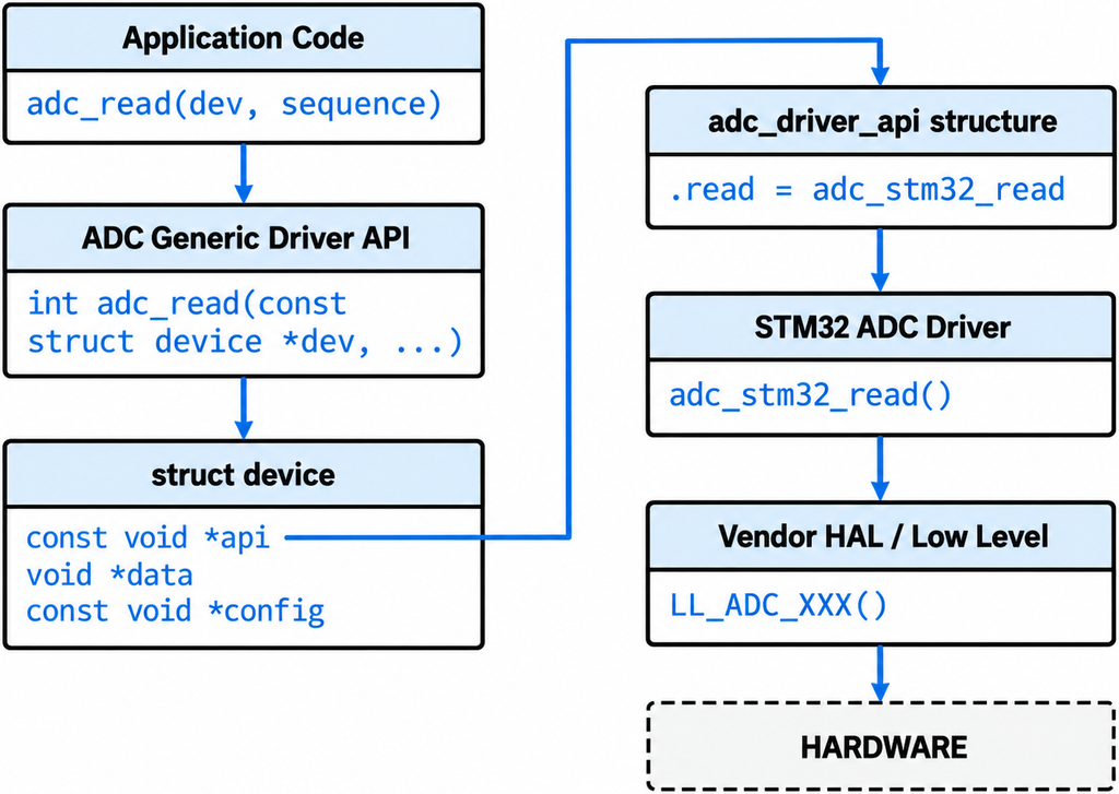
};The code below accesses an ADC device through Zephyr’s Device Model and Devicetree. DT_ALIAS(myadc) obtains the Devicetree node referenced by the myadc alias, while DT_CHILD(…, channel_3) selects ADC channel 3 under that device. DEVICE_DT_GET() retrieves the corresponding Zephyr struct device object so the application can later call generic ADC APIs such as adc_read(). Finally, ADC_CHANNEL_CFG_DT() automatically creates the channel configuration from properties defined in the Devicetree, avoiding the need to manually specify settings such as channel ID, gain, reference, and acquisition time.
#include <zephyr/kernel.h>
#include <zephyr/drivers/adc.h>

// prj.conf -> CONFIG_ADC=y
//          -> CONFIG_PRINTK=y

#define MY_ADC_NODE DT_ALIAS(myadc)
#define MY_ADC_CH_NODE DT_CHILD(MY_ADC_NODE, channel_3)

static const struct device *const adc_dev =
    DEVICE_DT_GET(MY_ADC_NODE);

static const struct adc_channel_cfg ch_cfg =
ADC_CHANNEL_CFG_DT(MY_ADC_CH_NODE);The code below prepares the ADC conversion result buffer and sampling sequence. sample is a 16-bit variable used to store the converted ADC value. The adc_sequence structure tells Zephyr which ADC channel to sample using .channels, where BIT(ch_cfg.channel_id) creates the channel bitmask. .buffer points to the memory where the result will be stored, and .buffer_size specifies its size. Finally, .resolution reads the ADC resolution, such as 12 bits, directly from the Devicetree property zephyr,resolution for that ADC channel.
uint16_t sample = 0;

struct adc_sequence seq = {
    .channels = BIT(ch_cfg.channel_id),
    .buffer = &sample,
    .buffer_size = sizeof(sample),
    .resolution = DT_PROP(MY_ADC_CH_NODE, zephyr_resolution),
    // .resolution = DT_PROP_OR(MY_ADC_CH_NODE, zephyr_resolution, 12),
};The code below configures the ADC channel, performs one ADC conversion, and prints the raw result. adc_channel_setup() applies the channel configuration stored in ch_cfg to the ADC device. If setup succeeds, adc_read() starts the conversion according to the previously defined adc_sequence and stores the result in sample. Both functions return a negative value if an error occurs. Finally, printk() displays the raw ADC sample value.
int err;

err = adc_channel_setup(adc_dev, &ch_cfg);
if (err < 0) {
    printk("Could not set up ADC channel (%d)\n", err);
    return 0;
}

err = adc_read(adc_dev, &seq);
if (err < 0) {
    printk("Could not read ADC (%d)\n", err);
}

printk("ADC raw: %" PRIu16, sample);The Devicetree overlay enables and configures the adc1 peripheral for ADC channel 3. pinctrl-0 = <&adc1_inp3_pa6> connects ADC1 channel 3 to pin PA6, while status = “okay” enables the ADC controller and st,adc-prescaler = <4> configures its clock prescaler. Inside channel@3, reg = <3> identifies ADC channel 3, and the zephyr,* properties define its gain, reference voltage, acquisition time, and 12-bit resolution. Finally, the aliases section assigns the name myadc to adc1, allowing the application to access this ADC using DT_ALIAS(myadc)
#include <zephyr/dt-bindings/adc/adc.h>

&adc1 {
    pinctrl-0 = <&adc1_in3_pa3>;
    pinctrl-names = "default";
    status = "okay";
    st,adc-prescaler = <4>;
    #address-cells = <1>;
    #size-cells = <0>;

    channel@3 {
        reg = <3>;
        zephyr,gain = "ADC_GAIN_1";
        zephyr,reference = "ADC_REF_INTERNAL";
        zephyr,acquisition-time = <ADC_ACQ_TIME_DEFAULT>;
        zephyr,resolution = <12>;
    };
};

/ {
    aliases {
        myadc = &adc1;
    };
};
my_led/
  ├── CMakeLists.txt
  ├── prj.conf
  ├── dts/bindings/
  │    └── <custom_name>.yaml
  ├── boards/
  │    └── <board_name>.overlay
  └── src/
└── main.cThe DT_PROP() macro retrieves the blinking delay from the Devicetree, while GPIO_DT_SPEC_GET() obtains the LED’s GPIO configuration.
#define BLINK_DELAY_MS DT_PROP(DT_ALIAS(myled), my_delay_ms)

const struct gpio_dt_spec led =
    GPIO_DT_SPEC_GET(DT_ALIAS(myled), custom_gpios);

gpio_pin_configure_dt(&led, GPIO_OUTPUT_INACTIVE);

while (1) {
		gpio_pin_toggle_dt(&led);
		k_sleep(K_MSEC(BLINK_DELAY_MS));
} The Devicetree overlay defines a custom LED node using the custom-led binding, configures GPIOE pin 13 as an active-high output, and sets the LED blinking delay to 1000 ms through the my-delay-ms property. The myled alias allows the application to reference the LED node using DT_ALIAS(myled). Additionally, the overlay configures the external high-speed oscillator (HSE) to 25 MHz and sets the PLL parameters to control the STM32 microcontroller’s clock frequencies.
/ {
	custom_led0: led0 {
		compatible = "custom-led";
		custom-gpios = <&gpioe 13 GPIO_ACTIVE_HIGH>;
		my-delay-ms = <1000>;
	};

	aliases {
		myled = &custom_led0;
	};
};

&clk_hse {
	clock-frequency = <DT_FREQ_M(25)>;
};

&pll {
	div-m = <25>;
	mul-n = <336>;
	div-p = <2>;
	div-q = <7>;
};This YAML file defines a custom Devicetree binding named custom-led in Zephyr RTOS, specifying the properties required to configure an LED and its blinking interval. The custom-gpios property uses the phandle-array type to identify the LED’s GPIO controller, pin number, and configuration flags, and is marked as required. The optional my-delay-ms property uses an integer to define the blinking delay in milliseconds, with a default value of 500 ms if not explicitly specified in the Devicetree.
compatible: custom-led

description: Custom node describing a single LED GPIO and a blink delay

properties:
  custom-gpios:
    type: phandle-array
    required: true
    description: LED GPIO
  my-delay-ms:
    type: int
    required: false
    default: 500
    description: Blink delay in milliseconds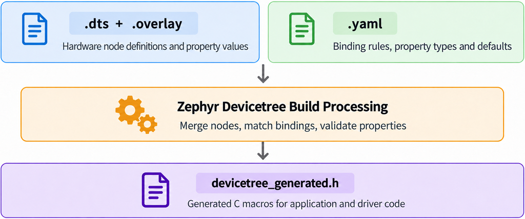
[1] Zephyr RTOS Cookbook
[2] Zephyr Project Documentation – Device Driver Model
[3] Zephyr Project Documentation – ADC API
[4] Zephyr Project Documentation – GPIO API
Back to top of the page